
Search history
Clear allSearch by image
XDrag and drop an image here or upload an image
Max 5MB per image
UploadSign In | Join
Search history
Clear allSearch by image
XDrag and drop an image here or upload an image
Max 5MB per image
UploadSign In | Join
X Email Mobile
Price Negotiable
A new item has been added to your Shopping Cart. You now have items in your Shopping Cart.
Our store specializes in a variety of high-power power supplies, true sine wave inverters, car inverters, electric vehicle inverters, solar controller products. Original factory products, quality assurance.
【Product Features】
1. Accurate discharge control using the discharge rate characteristics of the battery to correct. The end-of-discharge voltage is corrected by the discharge rate curve.
Control points eliminate the inaccuracy of simple voltage control over-discharge, in line with the inherent characteristics of the battery, namely different
Discharge rates have different termination voltages.
2. With the use of a microcontroller and specialized software, it achieves intelligent control.
3. Overcharge, overdischarge, electronic short circuit, overloading protection, and unique anti-reverse protection are all fully automatic controlled.
All the above protection measures do not damage any parts and do not burn the insurance.
4. The charge circuit uses a series PWM (Pulse Width Modulation) configuration, resulting in less voltage loss compared to a charge circuit using diodes.
Reduced by nearly half, the charging efficiency is 3%-6% higher than that of non-PWM, which increases the battery life. The over-discharge recovery charging is improved.
Normal direct charging and floating charge automatic control ensure a longer system lifespan; it also features high-precision temperature compensation.
5. Intuitive LED light-emitting diodes indicate the current battery status, allowing users to understand the usage condition.
6. All controls are equipped with industrial-grade chips (only applicable to controllers with the I industrial grade), capable of operating in extreme cold, high temperatures, and
The device operates smoothly in humid environments. It also uses crystal oscillator timing control, which provides precise timing control.
7. The potentiometer adjustment control set point has been canceled, and the Flash memory is used to record each working control point, making the setting digital.
Removed factors such as potentiometer vibration misalignment and temperature drift that cause errors in control points, reducing accuracy and reliability;
8. The device features a digital LED display and a one-button operation for all settings, making it extremely convenient and intuitive to use.
9. It has two output options: DC output or 1 Hz strobe output. The strobe output is particularly suitable for LED traffic warning lights, etc.
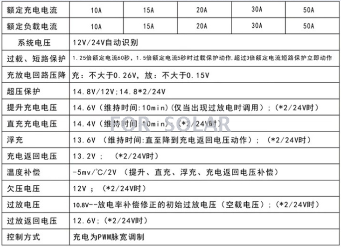
【Technical Parameters】
Model FLSC5I/10I/15I/20I
Rated Charging Current 5A/10A/15A/20A
Rated Load Current: 5A/10A/15A/20A
System voltage: 12V; 24V/12V automatic conversion
Overload and short-circuit protection: 1.25 times the rated current for 60 seconds. Overload protection acts when the current is 1.5 times the rated current for 5 seconds.
≥3 times rated current short-circuit protection operation
Empty load loss ≤6 mA
Charging circuit voltage drop is not greater than 0.26V
Discharge circuit voltage drop is not greater than 0.15V
Overpressure protection 17V, ×2/24V;
Operating Temperature: Industrial Grade: -35°C to +55°C (Suffix I);
Increase charging voltage to 14.6V; ×2/24V; (Duration: 10min) (Only called when there has been a discharge).
Direct charging voltage: 14.4V; ×2/24V; (Duration: 10 minutes)
Floating charge 13.6V; ×2/24V; (Maintenance time: until the action of the charging return voltage)
Charging return voltage 13.2v; ×2/24V;
Temperature Compensation -5mV/°C/2V (Boost, Direct Charge, Floating Charge, and Charge Return Voltage Compensation)
Undervoltage 12.0V; ×2/24V;
Overdischarge voltage 11.1V - initial overdischarge voltage (empty voltage) corrected by discharge rate compensation; ×2/24V;
Over-discharge return voltage 12.6V; ×2/24V;
Control Mode: Charging by PWM (Pulse Width Modulation)
Installation and Usage:
Preparation for Wiring: It is recommended to use multiple-strand copper-core insulated wire. First, determine the length of the wire. Ensure that the installation position is taken into account, and try to reduce the length of the wiring as much as possible to reduce electrical loss. Follow the principle of not exceeding the maximum length specified.4A/mm²Select the cross-sectional area of the copper wire based on the current density, and strip the connector on the controller side.5mmThe insulation.
Update time:


TOP


