Search history
Clear allSearch by image
XDrag and drop an image here or upload an image
Max 5MB per image
UploadSign In | Join
Search history
Clear allSearch by image
XDrag and drop an image here or upload an image
Max 5MB per image
UploadSign In | Join
X Email Mobile
A new item has been added to your Shopping Cart. You now have items in your Shopping Cart.


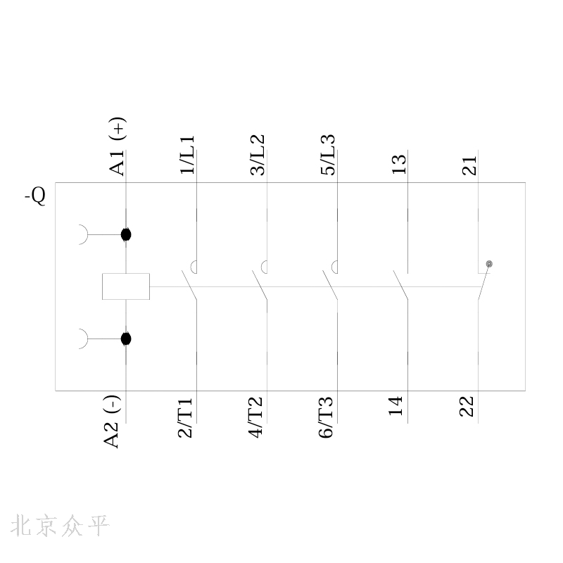
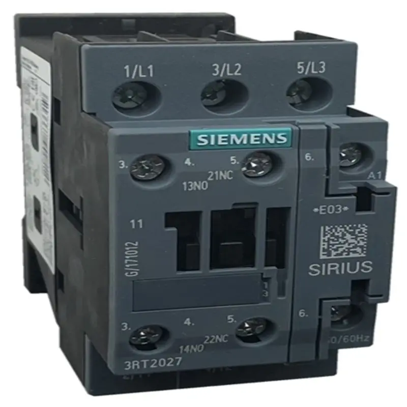
Power contactor, AC-3e/AC-3, 32 A, 15 kW/400 V, 3-pole, 24 V DC, auxiliary contact: 1
Normally open contact+1 normally closed contact, bolt end, feet: S0
Product brand name SIRIUS
Product name power contactor
Product Type Name 3RT2
Comprehensive technical data
Structural ruler s0 of contactor
Product expansion
● No function module for communication
● The auxiliary switch is
When loss power [W] current is measured,
● 6.3 W at AC in hot transport state.
● 2.3 W for each electrode in thermal transport state at AC.
● Typical load current share is 5.9 W.
Loss power calculation type electrode correlation orthomorphism
isolation voltage
● The pollution degree of the main circuit is 690 V at 3 o'clock.
● The measured value of auxiliary circuit pollution degree 3 is 690 V.
Impact resistance voltage energy
● The measured value of the main circuit is 6 kV.
● Measured value of auxiliary circuit is 6 kV.
The maximum allowable voltage for safety isolation conforms to EN between the coil and the main contact.
60947-1
400 V
When resisting the impact of impact waves
● 10g/5 ms, 7,5g/10 ms at DC.
Impact-resistant sinusoidal impact
● 15g/5ms and 10g/10ms at DC.
Mechanical service life (switching cycle)
● Typical contactor 10 000 000
● Typical 5,000,000 contactors with electrically adapted auxiliary switch blocks
● Typical contactor with auxiliary switch block 10 000 000
The reference mark conforms to IEC 81346-2:2009 Q.
RoHS directive (period) 10/01/2009
environmental conditions
The installation degree exceeds the maximum of 2 000 m above the level.
ambient temperature
● During transportation-25 ...+60 C
● Storage period-55 ...+80 C.
The maximum relative air humidity is 10%
When the relative air humidity is 55℃, the maximum value is 95% according to IEC 60068-2-30.
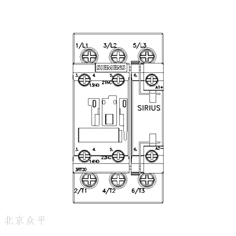
Mount/fix/outline ruler
The installation position can be vertically installed and rotated by+/-180 degrees, and can be tilted forward and backward by+/-22.5 degrees in vertical installation.
Fastening type: Screw fastening and fastening fastening on 35mm installation guide rail according to DIN EN 60715.
Degree 85 mm
Width 45 mm
Depth 107 mm
The spacing must be observed
● Single-row mounted
—10 mm forward.
-10 mm upward.
—10 mm downward.
—0 mm laterally
● To the grounding part
—10 mm forward.
-10 mm upward.
—6 mm laterally
—10 mm downward.
● To components with voltage
—10 mm forward.
-10 mm upward.
—10 mm downward.
—6 mm laterally
Update time:


TOP