Search history
Clear allSearch by image
XDrag and drop an image here or upload an image
Max 5MB per image
UploadSign In | Join
Search history
Clear allSearch by image
XDrag and drop an image here or upload an image
Max 5MB per image
UploadSign In | Join
X Email Mobile
Yiwu Zhongli Electronics Co., LTD. 14yr.
Contacts 黄华忠 Chat
Mobile 86-13566764473
E-mail huanglilidzc@126.com
WeChat 13566728436
Prices are for reference only. Please call 13566728436 or contact QQ 519869618 for details.
| Type: | Indoor TV antenna | Frequency Range: | 400 (MHz) |
| Output Impedance: | 75-300(Ω) | Model: | 128 |
| Remote control range: | 0 (m) | Brand: | zhong |
| Working Voltage: | 0 Volts | Standing Wave Ratio ≤: | 0 (dB) |


|
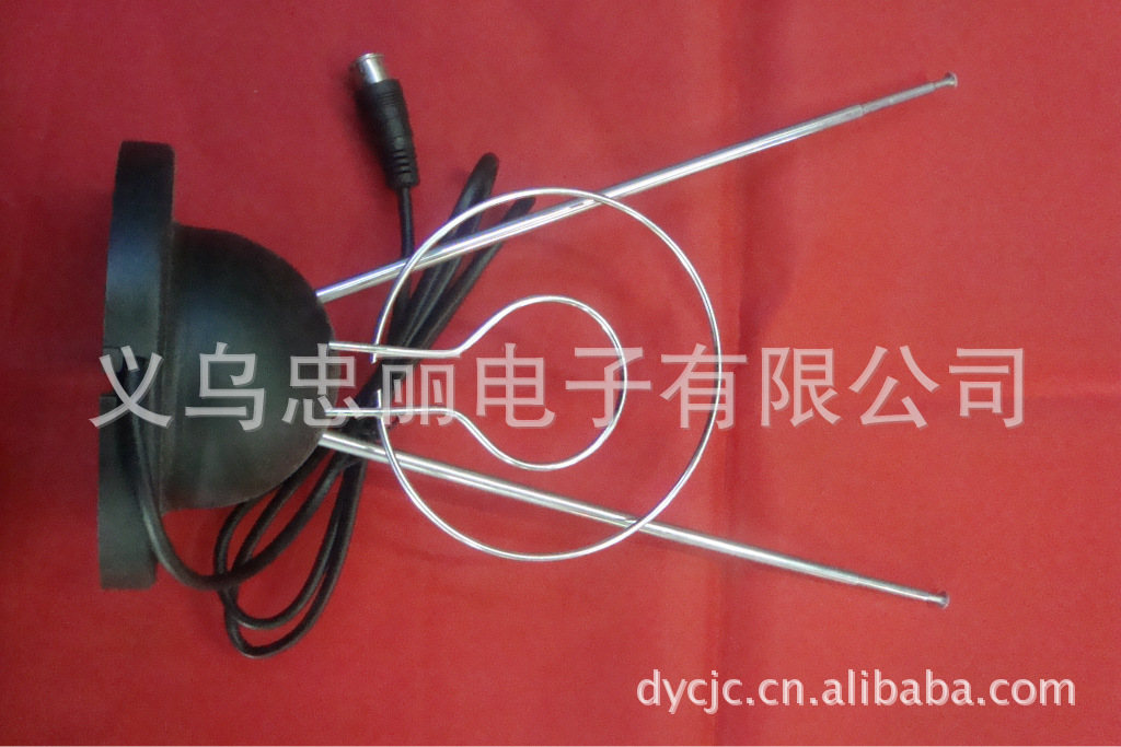
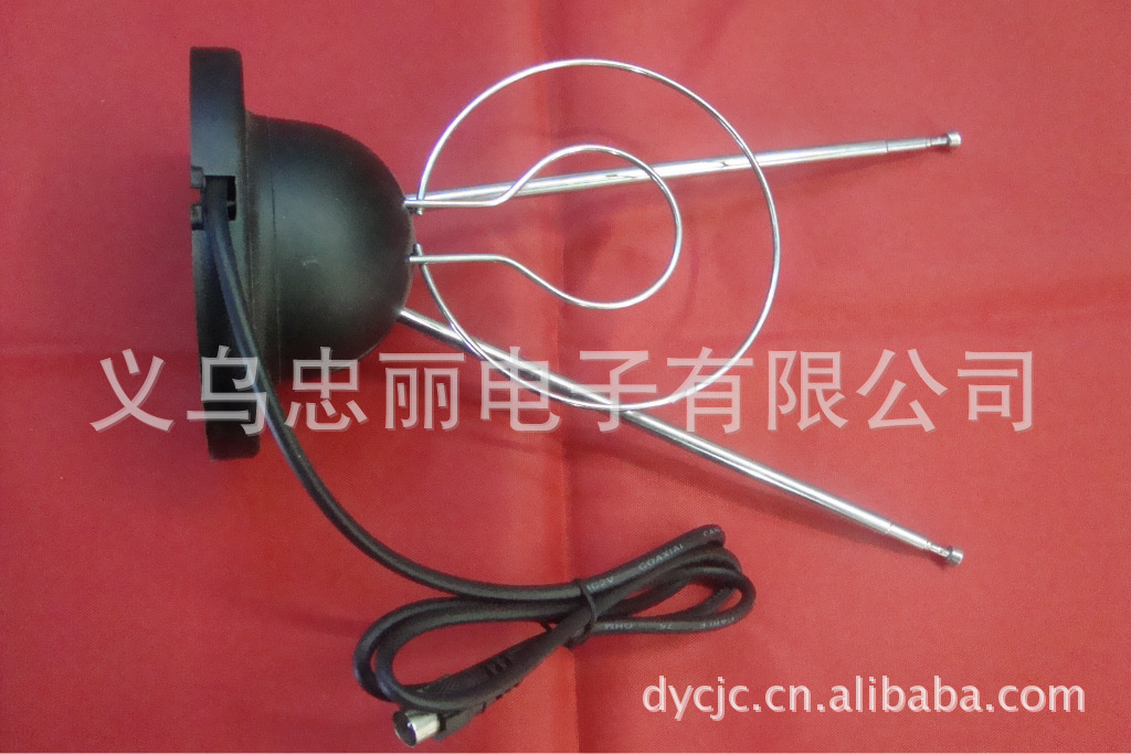
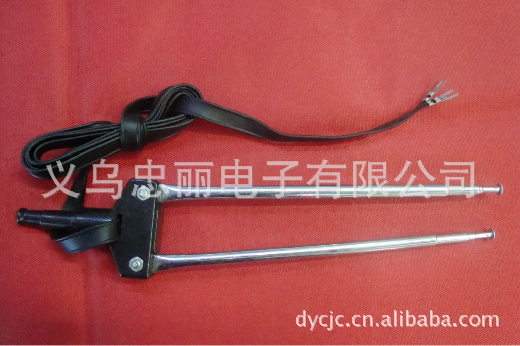
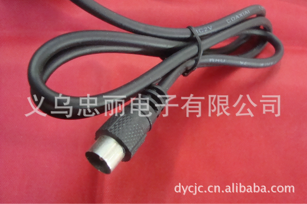
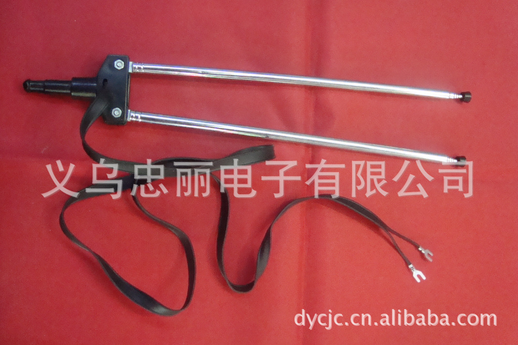
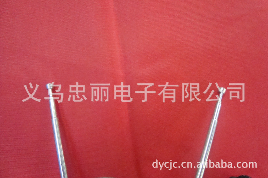
Indoor TV antenna
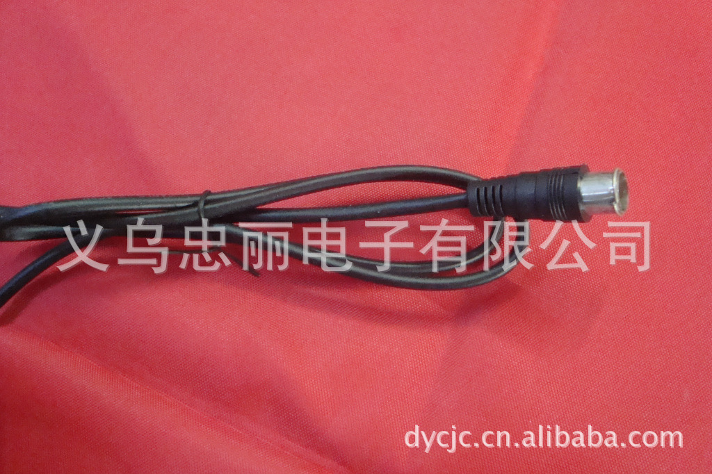
Our company is equipped with various antenna poles and antennae, including rabbit antennae, indoor and outdoor antennas.Please provide the Chinese text you want to translate, and I will translate it into English for you.Professional design and production of various antenna poles. Also, we can design and produce according to customer requirements. The handle head can be made of plastic.Please provide the Chinese text you want to translate, and I will translate it into English for you.Zinc alloyPlease provide the Chinese text you want to translate, and I will translate it into English for you.Aluminum.The tail can be rabbit ears.Please provide the Chinese text you want to translate, and I will translate it into English for you.goat's horn180Screw360Degree rotation screw. Number of pulleys: 3-5Section, the number of sections can also be made according to the requirements. Pull rod diameter: 6mm/7mm 圆环:2/3Can be custom-made according to requirements. Plug in:flat wirePlease provide the Chinese text you want to translate, and I will translate it into English for you.circle linePlease provide the Chinese text you want to translate, and I will translate it into English for you.And the length can be custom-made according to requirements.."The standard length is0.85m. "The plug is there.:9.5"public head,FQuick Connect,FSlow insertion. The model is contractible at will.Please provide the Chinese text you want to translate, and I will translate it into English for you.Signal Stable. Internal packaging: Blister packs, hanging cards, color boxes, and colorPVCBag, standardPVCThe bag can also be made according to the samples provided by the guests. Outer Packaging: Cardboard Box
|
The Working Principle of a Television Antenna
The relationship between VSWR (Voltage Standing Wave Ratio) and return loss
1) What is the working principle and function of the antenna?
Answer: Antennas are an indispensable part of wireless communication, and their basic function is to radiate and receive radio waves. When transmitting, they convert high-frequency currents into electromagnetic waves; when receiving, they convert electromagnetic waves into high-frequency currents.
(2)What are the various types of antennas?
Answer: There are numerous types of antennas, mainly classified in the following ways: By purpose, antennas can be divided into base station antennas (base station antenna) and mobile antennas (mobile portable antennas); By operating frequency bands, they can be classified into extremely low frequency (ELF), low frequency (LF), medium frequency (MF), high frequency (HF), very high frequency (VHF), and microwave; By direction, they can be classified as omnidirectional and directional antennas.
How to choose an antenna?
Answer: Antennas are an important part of the communication system, and their performance directly affects the indicators of the communication system. When choosing antennas, users must first focus on their performance. Specifically, there are two aspects, the first is to choose the antenna type; the second is to choose the electrical performance of the antenna. The significance of choosing the antenna type is: the directional pattern of the selected antenna meets the requirements of the electrical wave coverage in the system design; the requirement for choosing the electrical performance of the antenna is: the electrical indicators such as the frequency bandwidth, gain, rated power of the antenna meet the system design requirements. Therefore, it is best for users to contact the manufacturer for consultation when choosing antennas.
What is the gain of a antenna?
Answer: Gain is one of the main indicators of antennas. It is the product of the directional coefficient and the efficiency, and it reflects the size of the antenna's radiation or reception of electromagnetic waves. The choice of gain size depends on the requirements of the system design for the electromagnetic wave coverage area. Simply put, under the same conditions, the higher the gain, the farther the electromagnetic wave can be transmitted. Generally, base station antennas use high-gain antennas, while mobile station antennas use low-gain antennas.
What is the voltage standing wave ratio?
Answer: When the input impedance of the antenna and the characteristic impedance of the feedline are not consistent, the reflected waves and incident waves superimposed on the feedline form magnetic waves. The ratio of the maximum and minimum adjacent voltages is the voltage standing wave ratio, which is the basis for testing the transmission efficiency of the feedline. If the voltage standing wave ratio is less than 1.5 at the working frequency, and the voltage standing wave ratio is less than 1.2, the voltage standing wave ratio is too large, which will shorten the communication distance, and the reflected power will return to the transmitter power amplifier part, which is easy to burn out the power amplifier tube and affect the normal operation of the communication system. Voltage standing wave ratio: 1.0 1.1 1.2 1.5 2.0 3.0 Reflected power%: 0 0.2 0.8 4.0 11.1 25.0 Transmission power%: 100 99.8 99.2 96 88.9 75.0
What is the directionality of a antenna?
Answer: Antennas have different radiation or receiving capabilities in different directions of space, which is the directionality of the antenna. The directionality of the antenna is usually measured by the pattern. Antennas that have no maximum direction in terms of radiation and reception on the horizontal plane are called omnidirectional antennas, and those with one or more maximum directions are called directional antennas. Omnidirectional antennas, due to their lack of directionality, are often used in the central station of point-to-multipoint communication. Directional antennas, due to their maximum radiation or receiving direction, concentrate energy, and the gain is relatively higher than that of omnidirectional antennas. They are suitable for long-distance point-to-point communication, and at the same time, due to their directionality, they have stronger anti-interference capabilities.
How to understand the bandwidth of an antenna?
Answer: The electrical parameters of antennas are generally related to the operating frequency, and the frequency variation range allowed by the electrical parameter indicators is the operating frequency bandwidth of the antenna. Generally, the operating bandwidth of omnidirectional antennas can reach 3-5% of the working frequency range, and the operating bandwidth of directional antennas can reach 5-10% of the working frequency.
How to select cables and their lengths?
Answer: Mobile communication systems often use coaxial cables with a characteristic impedance of 50 ohms as feedlines. In order to effectively transmit electromagnetic waves to the antenna interface, it is necessary to minimize the transmission loss of the feedline. The transmission loss depends on the cable diameter and length. The larger the cable diameter at the same frequency, the smaller the loss, and the longer the cable, the larger the loss. In principle, the transmission loss of the cable should not exceed 3 dB. The following table lists the attenuation values (db/m) of commonly used cables. Users can reasonably choose the cable model and length according to their own circumstances. Frequency Model 150MHz 400MHz 900MHz SYV-50-7 0.121 0.203 0.295 CTC-50-7 0.060 0.100 0.165 CTC-50-9 0.050 0.085 0.135 CTC-50-12 0.040 0.060 0.105 Imported 10D-FB 0.040 0.070 0.110
How to choose the location for antenna installation?
Answer: Due to the influence of terrain and environment, the electromagnetic waves received by the antenna are the superposition of direct waves, reflected waves, and scattered waves. This result determines the amplitude and phase of the field strength at the receiving point, and it directly affects the application effect of the antenna. Therefore, when selecting the location for antenna installation, the following aspects should be considered: 1. The transmission or receiving direction of the antenna should avoid obstacles (buildings, towers, bridges, etc.); 2. The location for antenna installation should be as far away as possible from the source of interference (high-voltage lines, flight routes, towers, highways, etc.); 3. The antenna should be as high as possible on the nearby high point: 4. If several antennas work on the same tower, special attention should be paid to the left-right and up-down spacing between them to prevent mutual coupling affecting the system performance.
How should the antenna system be installed?
Answer: First, assemble the antenna, feedline, and associated components according to the product specifications. Then, at the support position of the antenna, fix it to the antenna bracket on the tower with a clamp, ensuring that the spacing between the antenna and the tower is greater than the use wavelength to reduce the impact of the tower on the antenna performance. At the antenna port, connect the feedline to the antenna using a connector (or cable head), and bend a circle with a diameter about 50 times the diameter of the feedline and fix it to the antenna bracket to avoid direct force on the connector causing a breakage or damage. (11) How is the antenna feed system waterproofed? Answer: The antenna and feedline are mainly connected by connectors, which are sealed with self-adhesive rubber sealing tapes. After stretching the tapes, they are wrapped around the connectors in a semi-tucked form, providing good sealing and waterproofing. Additionally, at the entrance of the feedline into the room, bend a U-turn to prevent rainwater from entering the indoor equipment along the feedline. (12) How is the antenna feed system tested? Answer: After the antenna feed system is set up, it should be tested by professional technicians using specialized testing equipment. Typically, a moving-iron power meter can be connected between the transmitter and the antenna feed system to measure the size of the transmitter power and reflected power, which can be used to judge whether the system is operating normally.
QQ 519869618
Update time:


TOP