
Search history
Clear allSearch by image
XDrag and drop an image here or upload an image
Max 5MB per image
UploadSign In | Join

Search history
Clear allSearch by image
XDrag and drop an image here or upload an image
Max 5MB per image
UploadSign In | Join
|
one no. 5 battery
5号电池1节 |
CN¥ 1.0 |
|
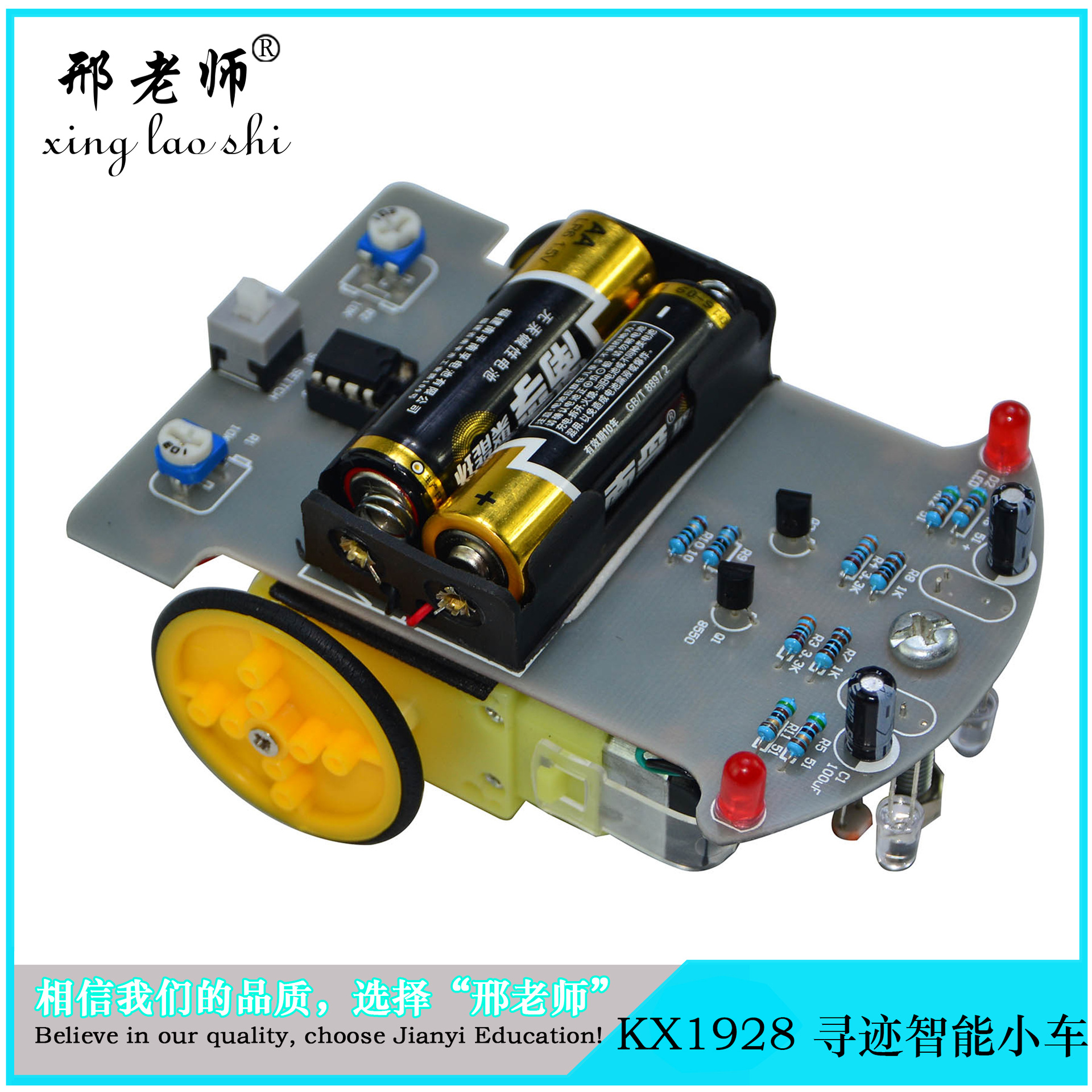
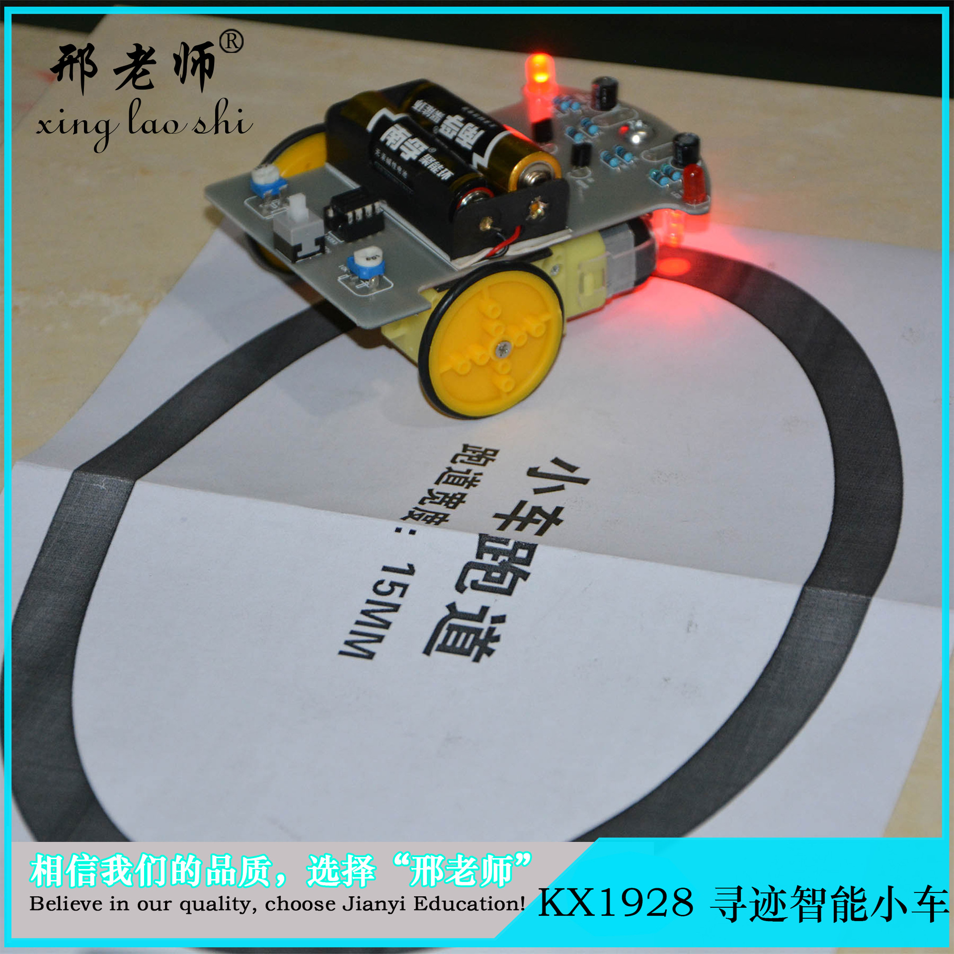
kx1928 line-following smart car
KX1928 寻迹智能小车 |
CN¥ 36.0 |
Contact the factory directly for detailed information: 1 5858 9 4 0 8 6
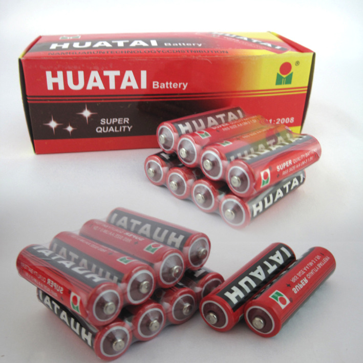
1 yuan equals one battery cell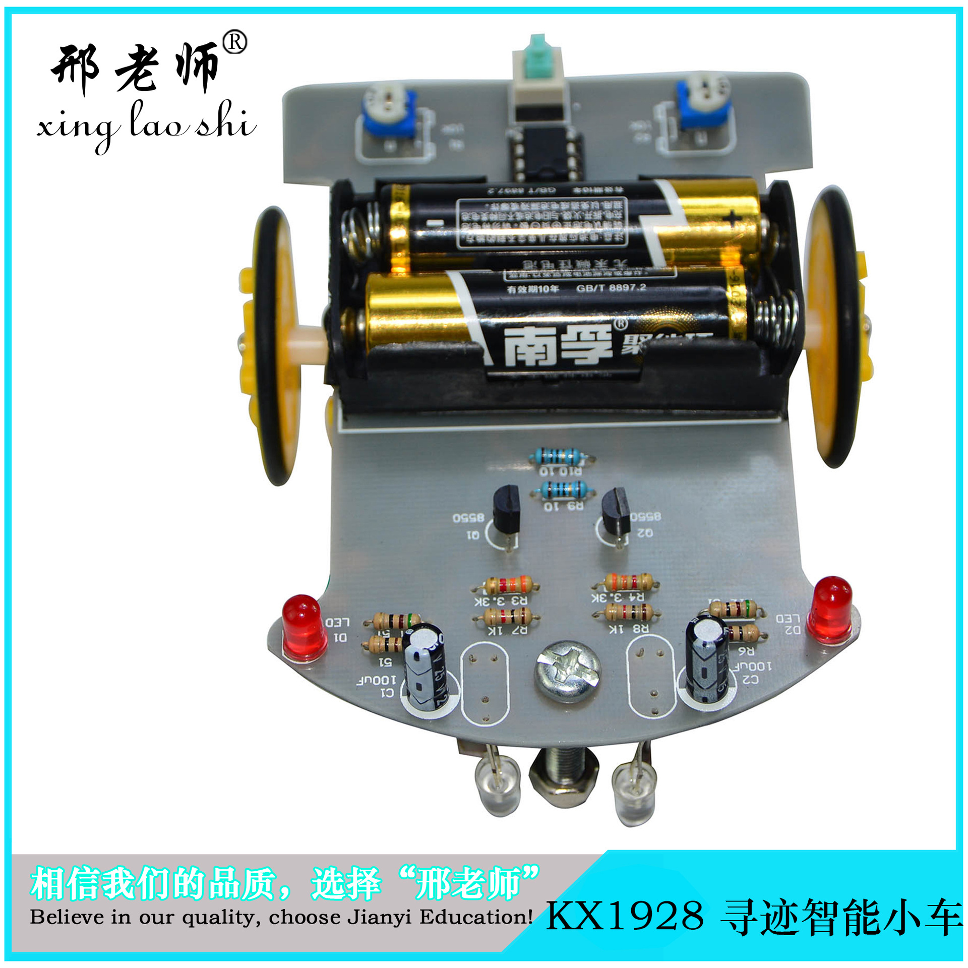

Product Name: KX1928 Tracking Smart Car
Model Number: KX1928
Size: 105*87*50 mm
Weight: Approximately 160g
Material: electronic components + circuit board + reduction motor + plastic accessories...
Color: Yellow
Does it use a battery: Yes
Packaging: 100 pcs
Box dimensions: 600*450*550mm
Smart Automatic Path-Finding Vehicle
As quality education gains increasing importance, many schools choose to use the construction of smart cars as their primary project. Smart cars are both engaging and interesting; they involve various subjects such as mechanical engineering, electronic fundamentals, sensor principles, automatic control, and even microcomputer programming. Students can significantly improve their ability to solve practical problems through hands-on practice. Moreover, smart cars serve as an excellent hardware platform—by adding some control circuits, projects such as track-following cars, fire-rescue robots, football robots, obstacle-avoiding robots, and remote-controlled cars can be implemented.
On the white surface, there is a black track 16 millimeters wide. Our tracking car can automatically travel along the black track. No matter how curved the track is, the car can still move automatically—it’s truly amazing! As we know, the reflectivity of light when it hits white and black objects is different. Here, red LEDs are used as the light source. The light reflects off the ground and reaches the photoresistor; by detecting changes in the resistance value of the photoresistor, we can determine whether the car is on the white area. If it is detected as a black track, it means the car has deviated. The motor on that side will slow down or even stop, and the green LED on that side will turn off. The car will then move in the opposite direction, ensuring it stays on the track all the time.

Parts Diagram: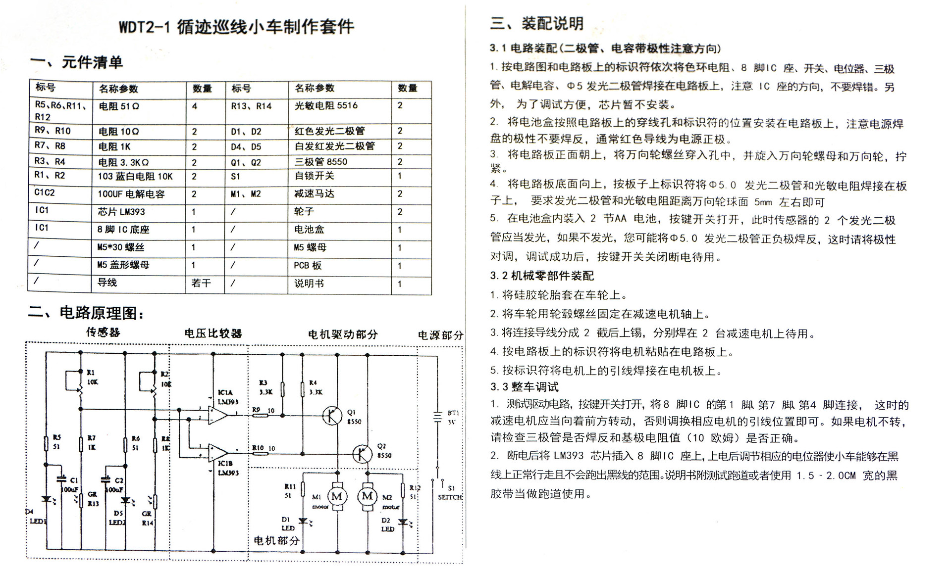
Circuit diagramFollowing the principle of starting with simplicity and progressing to complexity, we have developed a smart track-following car controlled by digital circuits. During the assembly process, we not only get familiar with mechanical principles but also gradually learn about electronic knowledge such as photoelectric sensors, voltage comparators, and motor drive circuits.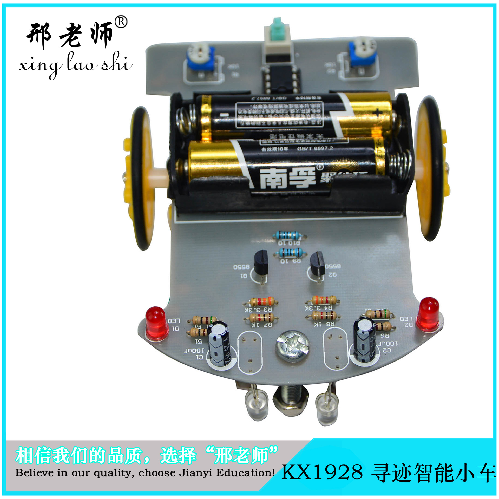
LM393Comparator integrated circuit
LM393It is a dual-channel voltage comparator integrated circuit, composed of two independent precision voltage comparators. Its function is to compare the two input voltages and adjust the output voltage based on their levels. There are two output states: near open circuit or pull-down to near low level. The LM393 uses open-collector output, so a pull-up resistor must be added to generate a high level output.
DC motor with reduction gears
If using a DC motor to drive the car, deceleration is essential; otherwise, if the speed is too high, the car runs too fast and it becomes impossible to control it. Moreover, without deceleration, the torque would be too low to even move the car. The specially customized motor we used has integrated reduction gears, which significantly reduces production complexity and is very suitable for our needs.
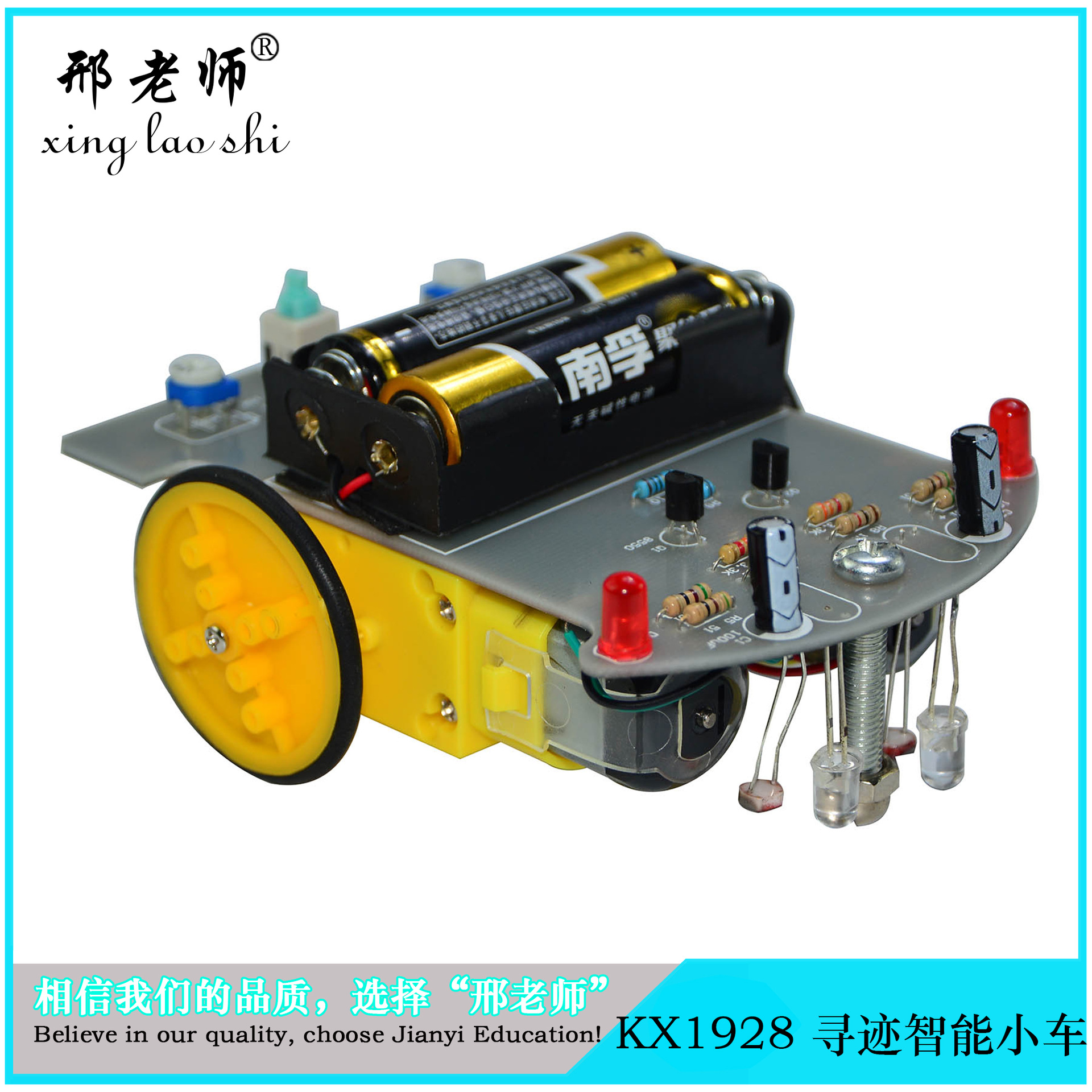
Let’s get familiar with the working principle diagram of the entire device. The LM393 constantly compares the magnitudes of the two photoresistors. When an imbalance occurs (for example, one side being pressed against a black track), it immediately controls one motor to stop rotating, while the other motor accelerates, allowing the vehicle to correct its direction and return to the correct path. The entire process is a closed-loop control, which enables rapid and sensitive operation.
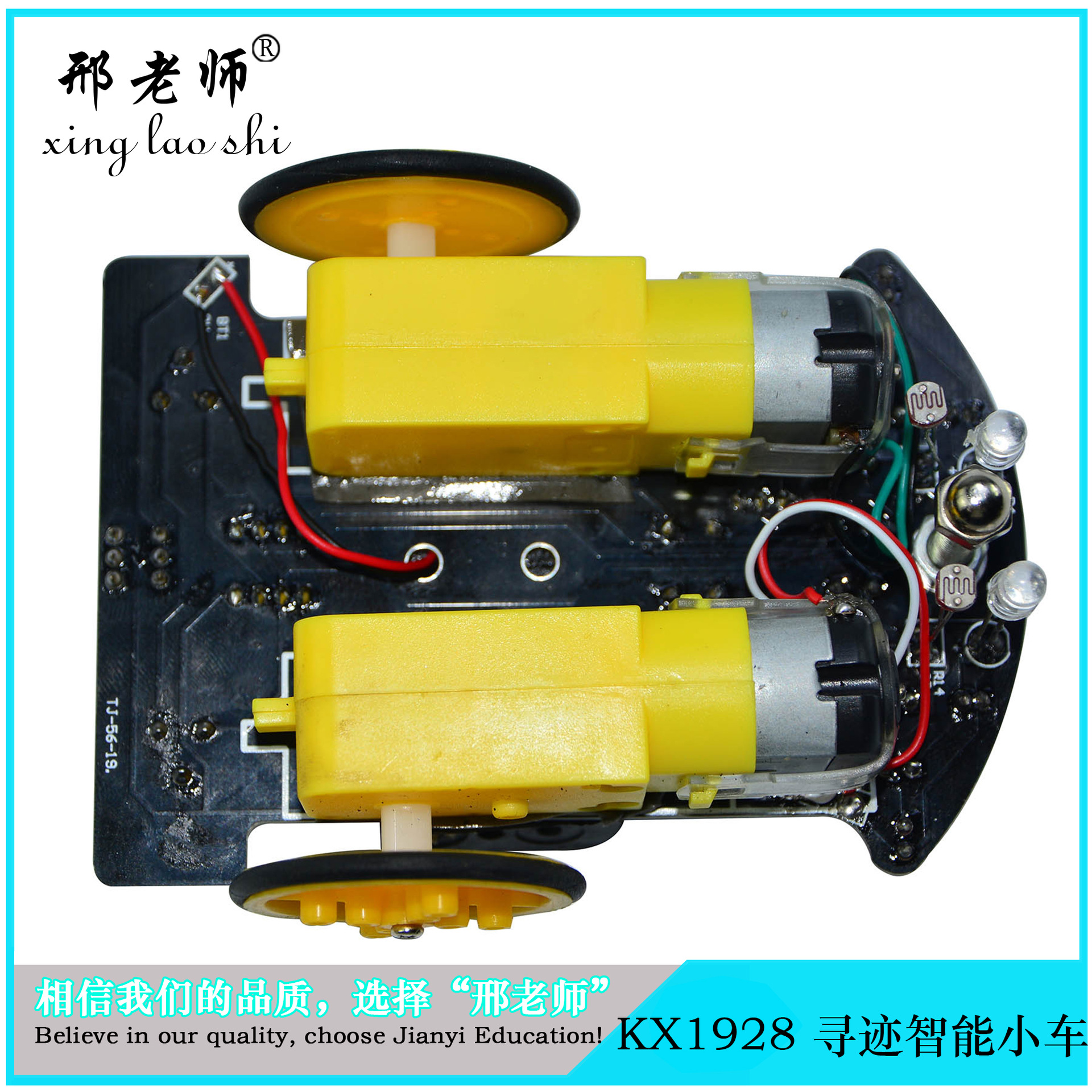
Step: Basic soldering for the circuit section
The circuit soldering section is relatively simple. Follow the principle of soldering components from low to high in height. Solder 8 resistors. When soldering, be sure to use a multimeter to verify that the resistance values are correct. For components with polarity, such as triodes, green indicator lights, and electrolytic capacitors, clearly identify the polarity. Try to follow the component orientation shown in our images during soldering. When soldering capacitors, insert the shorter lead as the negative terminal on the side shaded in the PCB markings. For green LEDs, note that the longer lead is the positive terminal. Also, do not solder for too long, as this may cause damage. D4, D5, R13, and R14 can be left unsoldered for now. Integrated circuit chips can also be left unconnected. After initial soldering, please check carefully to avoid mistakes due to carelessness.
Step 2: Mechanical Assembly
Insert the universal wheel screws into the PCB holes, and screw on the universal wheel nuts and universal wheel. The battery case is attached to the PCB using double-sided adhesive. The leads are passed through the reserved holes in the PCB and soldered onto the PCB; the red wire connects to the 3V positive power source, the yellow wire grounds, and any excess leads can be used for motor connections.
Wheel assembly
The mechanical component assembly can begin with the wheels. The wheels consist of three wheel segments: the inner segment has a circular hole at its center, the middle segment has a smaller diameter, and the outer segment has a circular hole at its center. The three wheel segments are secured with two screw nuts, and the motor shaft is fixed using black self-tapping screws. Next, a silicone tire is placed on the wheel. The motor leads are connected properly, and the wheel assembly is attached to the PCB using adhesive. Ensure there is sufficient space between the wheel and the PCB edges. The motor leads are welded to the PCB, and note that the leads should be left slightly longer to facilitate changing the lead order in case the motor rotates in the wrong direction.
Step 3: Install the photoelectric circuit
The photosensitive resistor and light-emitting diode (note the polarity) are installed on the PCB in reverse orientation, with a distance of approximately 5 millimeters from the ground. The distance between the photosensitive resistor and the light-emitting diode is also about 5 millimeters. It can be tested after powering on.
Step 4: Full Vehicle Testing
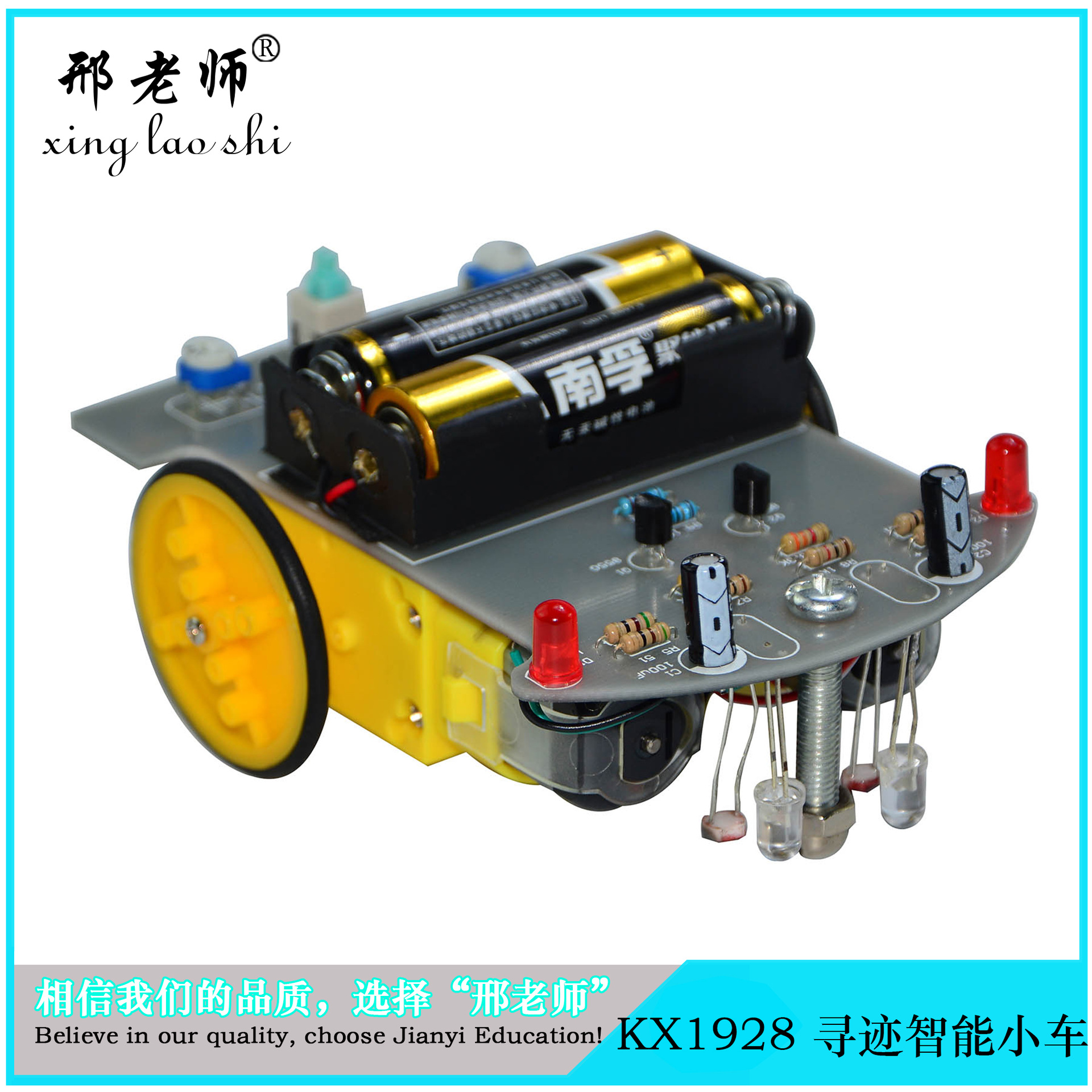
2 AA batteries are inserted into the battery compartment, the switch is set to the “ON” position. The correct driving direction of the vehicle is along the omnidirectional wheel direction. If the left photosensitive resistor is held down, the right wheel of the vehicle should rotate; if the right photosensitive resistor is held down, the left wheel should rotate. If the vehicle moves backward, the wiring of both motors can be swapped. If one side operates normally while the other moves backward, simply swap the wiring of the backward-moving side’s motor.
Special Notes: On the back of the assembly manual is a simple track for the tracking car. Customers can also directly apply 1.5–2.0 cm of black electrical tape to the ground to create a complex track, which makes it even more fun.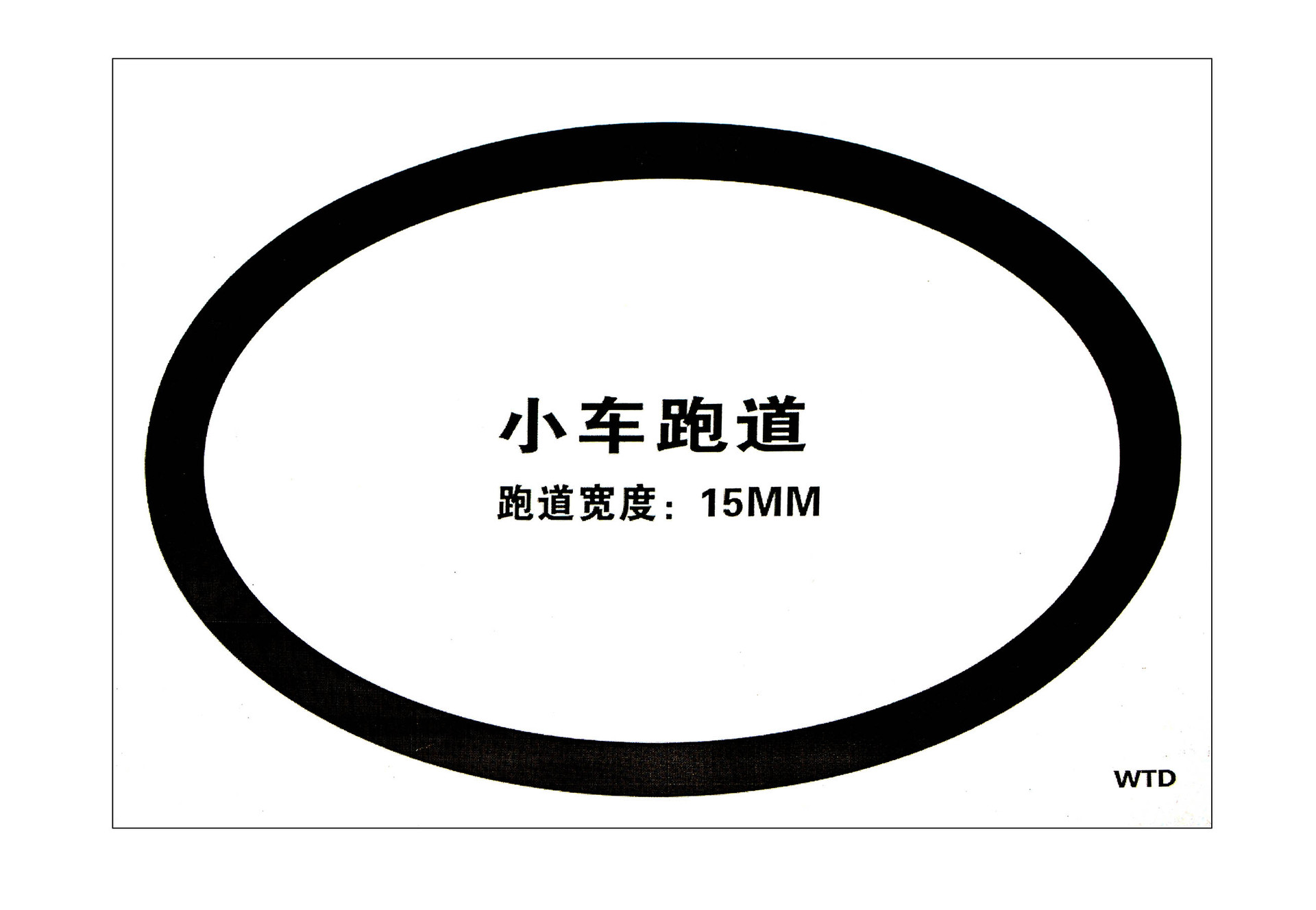
A intense and exciting smart car race was held.
The preliminary round took place in the laboratory
This is a competition that combines innovation, practice, knowledge, and fun.
All the students took out their carefully made cars.
Prepare to compete with the opponent
How can we make the car run faster?
How can we make the circuit of the small device more accurate?
The athletes have already undergone continuous practice and improvement
Improve and enhance the performance of the intelligent vehicle
Through unremitting effort and team collaboration
Make the car move on the track
According to the established route, track and race against time
With firm confidence, challenge oneself
Performing "Speed and Passion"
The smart car moves and turns on the track
Approaching the predetermined destination step by step
Carrying the athletes' beliefs and efforts, "speeding" along the track
The athletes' cars each have their own advantages.
Every detail reveals the resilience and passion of each competitor.
Come and check out the cars after the exterior beautification!





Zhejiang Jianyi Education Technology Co., Ltd.
Zhejiang Jianyi Education Technology Co., Ltd. (formerly Yifei Toys Factory)Established in 2007, the current brand names include “XING TEACHER” and “JIAN YI”. Through 10 years of relentless effort, the company has gradually matured. Our firm is a member of the Ministry of Education’s Teaching Equipment Industry Association and a key enterprise in Zhejiang Province’s teaching equipment sector. For three consecutive years, it was recognized by Jinhua City as a “Contract-Abiding and Creditworthy” entity, and in 2014, it was awarded the title of “Advanced Enterprise in Jinhua Teaching Instruments Industry” by Zhejiang Province.
Zhejiang Jianyi Education Technology Co., Ltd. is a high-tech enterprise that integrates modern scientific research and development of educational equipment, curriculum design, integrated teaching resources, and technical services. With its high-tech products and modern educational equipment, Zhejiang Jianyi Education Technology Co., Ltd. sells its products across the country and to Europe, America, Japan, South Korea, and other regions. After years of accumulation, the company has reached a certain scale. In terms of technological innovation, the company has professional designers who develop complete sets of educational products and upgrade existing products. In terms of production, management, and installation services, the company strictly adheres to the standards of the ISO9001 international quality assurance system. In marketing, the “Teacher Xing” products have been introduced to many provinces and cities in China and enjoy a good reputation. Over the years, it has provided high-quality, advanced, and professional series of modern teaching equipment and specialized R&D and customization services for the education sector. With excellent, highly qualified professionals, comprehensive after-sales service, high product quality, and a positive corporate image, the “Teacher Xing” educational and physical science series, chemistry series, energy, wind, geography, biology, art, and more products have won multiple bids in education bureau tenders. Zhejiang Jianyi Education Technology Co., Ltd. continues to uphold the business philosophy of “ultimate quality, diligent service, and sincerity in people,” maintain the “Teacher Xing” culture, build the “Teacher Xing” brand, and pursue the development strategy of the “Teacher Xing” enterprise. It provides excellent equipment and high-quality services for school teaching and research. We are willing to cooperate wholeheartedly with new and old friends at home and abroad, work together, and serve education with all our efforts and contribute to the education industry.

Please check that the circuit is unobstructed and all components are intact before assembly, as well as ensure all contact points are properly aligned. During assembly, be careful not to let glue get on your clothes or skin. Keep the components out of reach for younger siblings to prevent them from accidentally swallowing them! Do not play with them on your head, as the model may fall and hurt you!


Update time:


TOP


