
Search history
Clear allSearch by image
XDrag and drop an image here or upload an image
Max 5MB per image
UploadSign In | Join

Search history
Clear allSearch by image
XDrag and drop an image here or upload an image
Max 5MB per image
UploadSign In | Join
Yiwu Jiahe Optical Instrument Co., Ltd 15yr.
Contacts jiangyanling Chat
Mobile 13735650618
15268668906








All prices of products sold by this store are tax-exclusive, please contact customer service for an invoice!
Product Introduction:
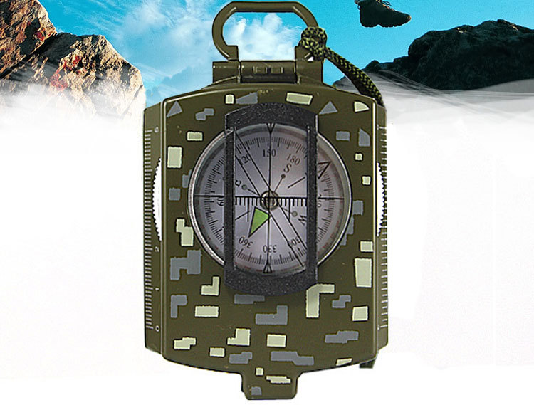
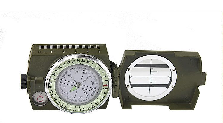
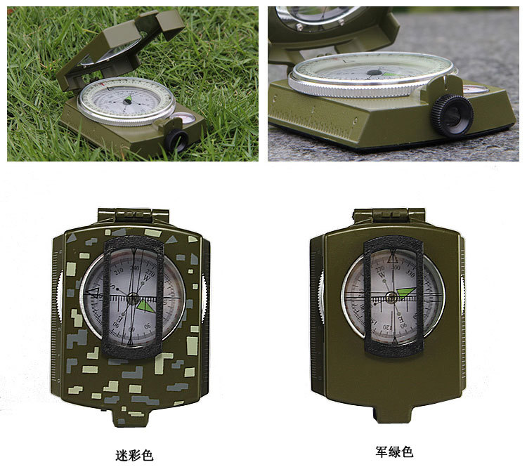
【Product Model]: K4 580 - Military Green. This is the price listed for items sold by our store; the misty color version costs an extra 1 yuan.
【Product Specifications】: 8.5*6.3*3.0 mm
【Product Weight】: 220 grams
【Product Material】: Zinc alloy
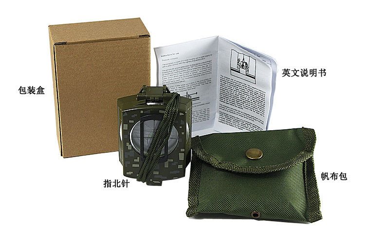
【Packaging Methods】: Bubble bag, cloth bag, colored box
【Packing Information】: 50 pieces per box. The prices listed for products in our store are tax-exclusive; please contact customer service for an invoice! 10 pieces per medium package.
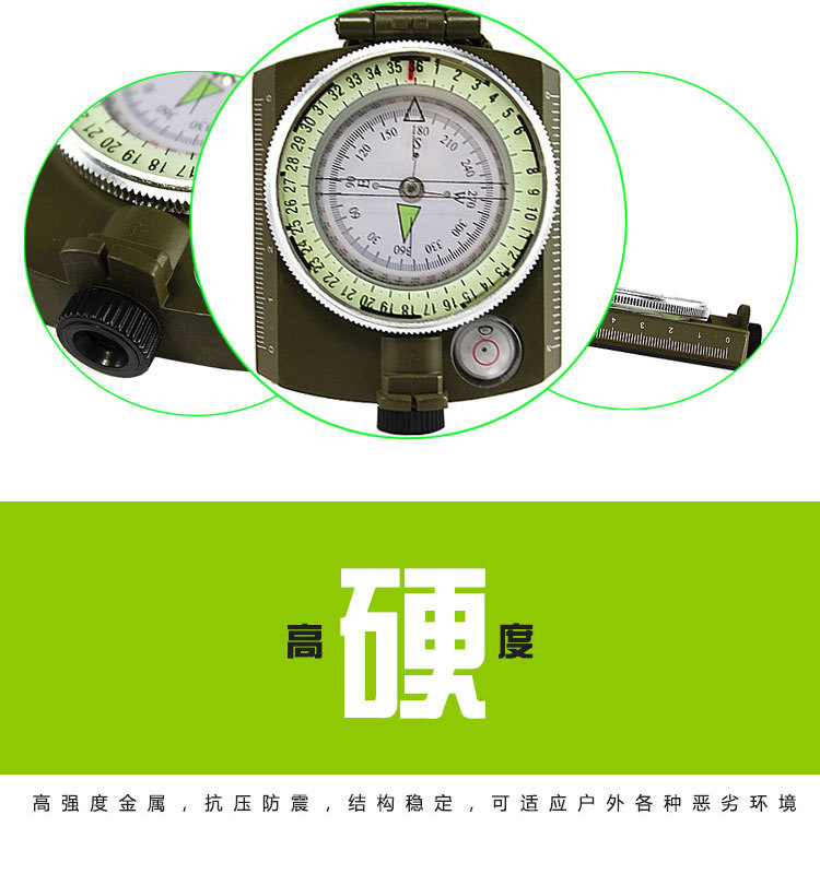
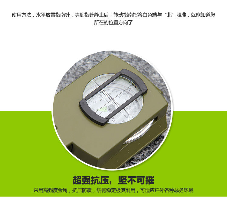
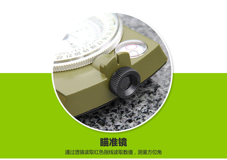
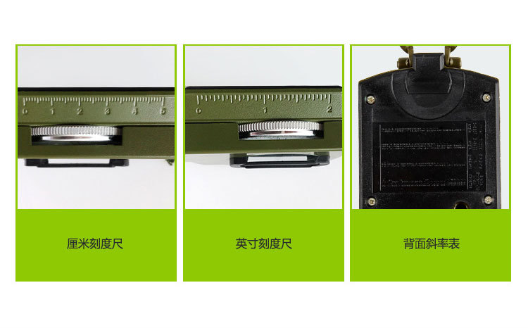
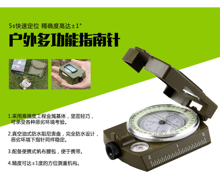
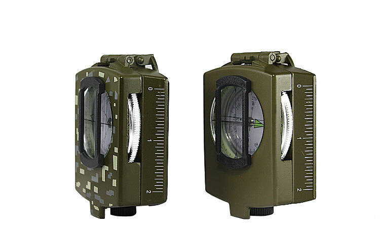
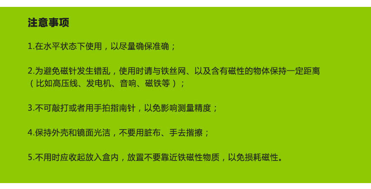
Construction and Performance: 1. Azimuth Measurement Mechanism: Composed of a compass, bearing knob, and sighting line. The outer ring of the azimuth scale uses a 360° division system with a minimum division value of 2°; the inner ring uses a 60–0° metric division system with a minimum division value of 0–20 metric units. The conversion between metric units and degrees is shown in the table. Measurement Accuracy: ±0–10 metric units. The prices of products sold by this store are tax-exclusive; please contact customer service for an invoice. ±1°. 2. Distance Estimator: Composed of a bearing knob and sighting line. The angle between the two tips of the sighting line and the center line of the bearing knob is 1–0° metric units. The distance between the two tips is 2.3–4.4 millimeters, and the distance between the bearing knob and the sighting line is 2.3–3.4 millimeters, forming a 1:1 ratio distance estimator. Measurement accuracy: 5%. 3. Pitch Angle Measurement Mechanism: Composed of a pitch indicator plate, pitch swing, and horizontal mirror. Its range is ±90°. Measurement accuracy: ±2.5°. 4. Coordinate Ruler: Composed of a long perpendicular side ruler and two short side rulers, with a ruler length of 12.0 millimeters. Measurement accuracy: ±0.5 millimeter. Usage Instructions: 1. Measuring Azimuth Angle: Unfold the compass, rotate the azimuth frame so that the scale lines on the azimuth glass align with the direction indicator. Place the horizontal mirror at a 45° angle, aim the single eye through the sighting line at the target, and observe the azimuth divisions on the opposite indicator plate where the N pole of the magnetic needle reflects from the mirror. This allows you to read the target azimuth angle. Then, use the right hand to rotate the azimuth frame so that the scale lines on the azimuth glass align with the N pole of the magnetic needle. The angle between the direction indicator and the scale lines on the azimuth glass is the target azimuth angle (calculated clockwise). Turn on the compass, mark the map (the map may not be needed for distance measurement), insert a pin at the reference point on the map, rotate the compass so that the edge of the side ruler touches the target point, and then you can determine the azimuth angle from the reference point to the target point. 2. Marking the Map: Unfold the compass, rotate the azimuth frame so that the scale lines on the frame align with the direction indicator (note the correction for magnetic declination). Place the compass flat on the map, with one end of the sighting line facing the Arctic pole of the map. Ensure the length of the coordinate ruler touches the magnetic meridian of the map. Rotate the map so that the N pole of the magnetic needle aligns with the scale lines on the azimuth glass. At this point, the map is marked. 3. Determining the Movement Direction to Hide the Target: Unfold the compass on the map so that the measuring ruler passes through the reference point on the map and the target. The direction indicator then indicates the intended movement direction. Rotate the orientation frame so that the (S, N) directions on the orientation glass match those on the map, then record the bearing angle reading indicated by the direction indicator. Face the direction indicator, pick up a compass, and turn your body so that the N pole of the magnetic needle aligns with the scale line on the orientation glass. At this point, align the compass with the aiming point through the sighting post; objects along this alignment line (such as trees or houses) can serve as auxiliary targets for navigation. Once the auxiliary target is identified, continue moving forward. Close the compass and put it in your bag, but do not rotate the orientation frame. After reaching an auxiliary target, find a new one to proceed toward until reaching the destination. Regularly check the direction reading along the way. 4. Given the spacing between targets, estimate the distance from the target to the standing point: ① Aim at the target using the left and right tips of the sighting post and the aiming post. Estimate the target distance using the 1:10 ratio formula based on the width of the space between the two tips. Distance from target to standing point (meters) = Width of target spacing (meters) × 1/10 × Multiplier of target spacing relative to the width of the two tips. Example: There is a road parallel to our position ahead. Calculate the distance between the road and the position. There are utility poles along the road, with a distance of 50 meters between them. The distance estimator shows 5 poles on the left and right sides, meaning the interval between each pair of poles is 1/4 of the distance between the two tips. Using the ratio formula: Distance between road and position = 50 × 1/10 × 4 = 200 meters. ② Use an auxiliary point to estimate the target distance: Aim at the target with the sighting post and aiming post, rotate the orientation frame so that the scale line aligns with the N pole of the magnetic needle, and record the bearing angle reading. Then turn left or right by a right angle (i.e., 15–0 degrees difference from the original bearing reading) to find an auxiliary point. Measure the distance from this auxiliary point to the standing point using step measurement or other methods. At the auxiliary point, use the compass to align with the original target through the sighting post and aiming post, again rotating the orientation frame so that the scale line aligns with the N pole of the magnetic needle, and record the reading. Determine the target distance based on the difference between the two bearing readings and the distance from the standing point to the auxiliary point, using Table 2. If the difference between the two bearing readings is 75–50 degrees (i.e., 45°), then the target distance equals the distance from the standing point to the auxiliary point. 5. Measure the pitch angle: Place the side facing down, aim at the target with the sighting post and aiming post, and the horizontal mirror reflects the pitch angle reading; or place the side on a flat surface and measure the inclination angle of that surface. 6. Measure altitude: Use a map and altimeter to determine the altitude. The horizontal distance from the standing point to the target as indicated on the map, combined with the pitch angle measured using a compass, can be used to determine the altitude via a altimeter or calculated using trigonometric functions. For example: To find the height between the base of a mountain and its summit. The horizontal distance between the summit and the standing point on the map is 100 meters. Using a compass, the elevation angle at the summit is 40°. Then, by consulting an altimeter at 100 meters and comparing it to 40°, the altitude is 83.91 meters. 7. Measuring the distance between any two points on a map: For maps with different scales, the relationship between the square grid side length and actual distance is calculated as follows: 1:2500 scale: Distance = (measured millimeters / 4) × 100 (meters) 1:5000 scale: Distance = (measured millimeters / 2) × 100 (meters) The prices listed for products sold by this store are tax-exclusive prices. Invoices must be requested from customer service. 1:10000 scale: Distance = measured millimeters 8. Magnetic declination measurement: ① The magnetic poles of the Earth are not exactly in the true north or south directions. Therefore, the direction indicated by a compass has a deviation angle from the true north or south. This deviation angle is called magnetic declination, and its value varies from place to place. When precise measurement is not required, the direction indicated by the compass can be considered as true north. When precise measurement is needed, the local magnetic declination should be checked first, and then the true north/south direction can be determined based on the compass indication. For instance, in Changsha, the magnetic declination is 2°41’ (W), meaning the north direction indicated by the compass is 2°41’ west of true north. ② Method for calculating magnetic declination anywhere. On clear nights, unfold the compass, rotate the bearing frame so that the (N) symbol on the bearing glass faces the direction indicator. Align the sighting tube, crosshairs, mirror, and night-light mark with the North Star, keeping the compass direction unchanged. Place the compass flat; the reading indicated by the compass’s north pole is the local magnetic declination. Maintenance: 1. When using or storing a compass, avoid proximity to ferromagnetic objects, high-voltage lines, and electromagnetic devices to prevent errors and reduce the compass’s sensitivity. 2. When not in use, keep the compass in a ventilated, dry place to prevent mold. 3. Do not bend the mirror or reverse-word plate to avoid affecting its accuracy. 4. When the surfaces become dirty, gently wipe them with white velvet cloth to maintain a smooth surface.
Features:
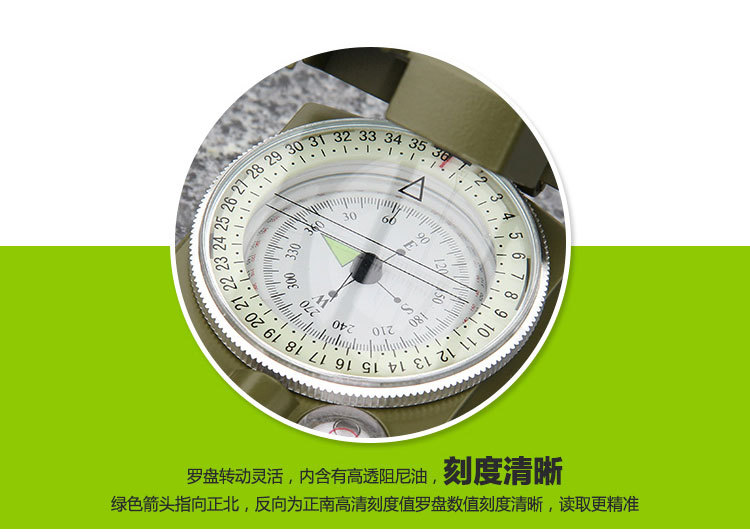
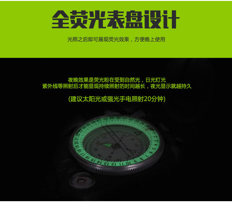
The damping oil pan design enhances the stability of the product; it features a fully sealed structure that is waterproof; and a level gauge improves accuracy, significantly reducing errors!
Update time:


TOP


