
Search history
Clear allSearch by image
XDrag and drop an image here or upload an image
Max 5MB per image
UploadSign In | Join

Search history
Clear allSearch by image
XDrag and drop an image here or upload an image
Max 5MB per image
UploadSign In | Join
X Email Mobile
 black
black
|
CN¥ 0.0 |
Zhejiang Yubu Electric Co., LTD 3yr.
Contacts:MAX Chat
Mobile:86-18867711136
E-mail:619588251@qq.com
Basic Introduction to Frequency Converters
1. Variable-frequency Drive (VFD), also known as a variable-speed drive or a drive controller, can be translated as Inverter (the same as the English word for inverter). A VFD is a type of adjustable-speed driving system that uses variable-frequency driving technology to change the frequency and amplitude of the AC motor's working voltage, smoothing the control of the AC motor's speed and torque. The most common type is an AC/AC converter with both inputs and outputs being AC electricity.
Before the advent of inverters, the application of adjusting motor speed required the use of direct current motors, or else involved using VS motors with built-in couplings to reduce the actual motor speed during operation. The inverter has simplified this process, reducing the size of the equipment and significantly lowering maintenance rates. However, the power lines and motor leads of inverters contain high-frequency switching signals, which can cause electromagnetic interference. Additionally, the power factor at the input side of the inverter is generally poor, leading to harmonic currents at the power supply end.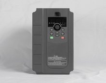 frequency converter" 或 "variable-frequency drive
The application scope of inverters is very wide, from small household appliances to large mining grinding machines and compressors. About one-third of the world's energy is consumed in the electric motors of constant-speed centrifugal pumps, fans, and compressors, and the market penetration rate of inverters is still not high. One of the main reasons for the significant improvement in energy efficiency is the use of inverters.
4. The technology of inverters is closely related to power electronics, including semiconductor switching elements, inverter topologies, control and simulation technology, and the progress of control hardware and firmware.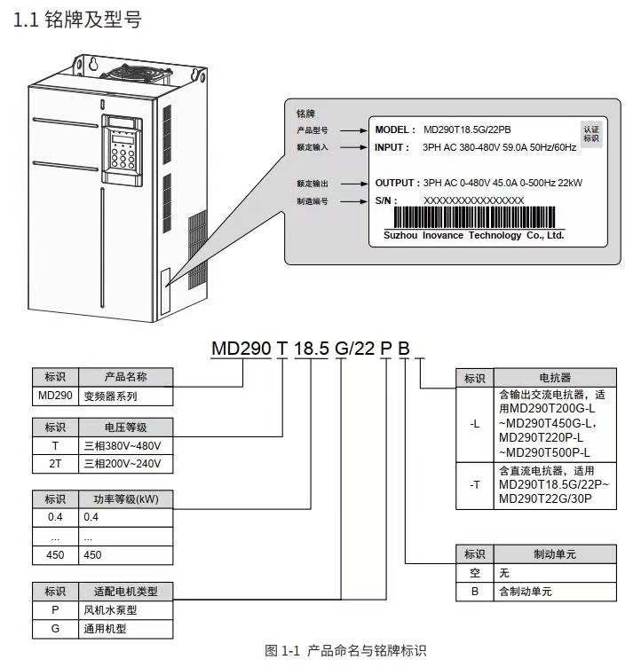
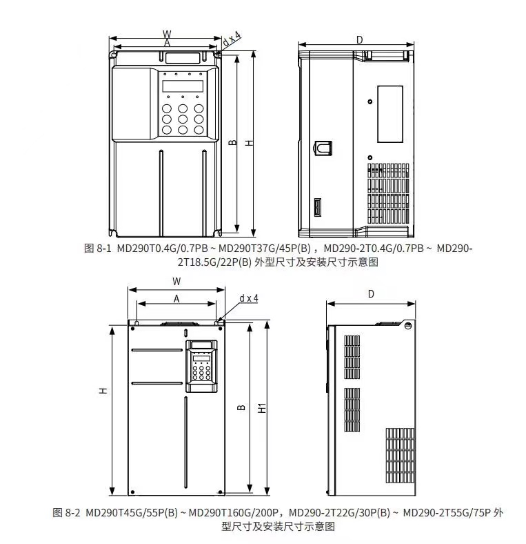
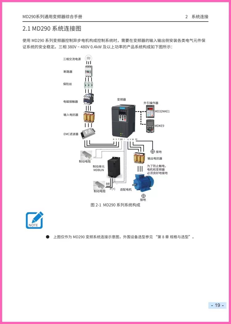

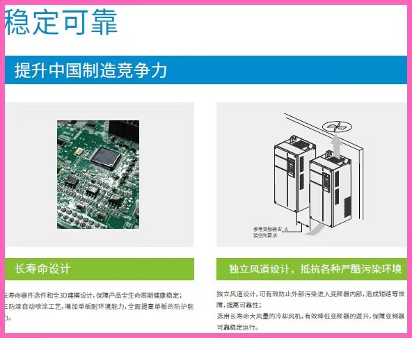
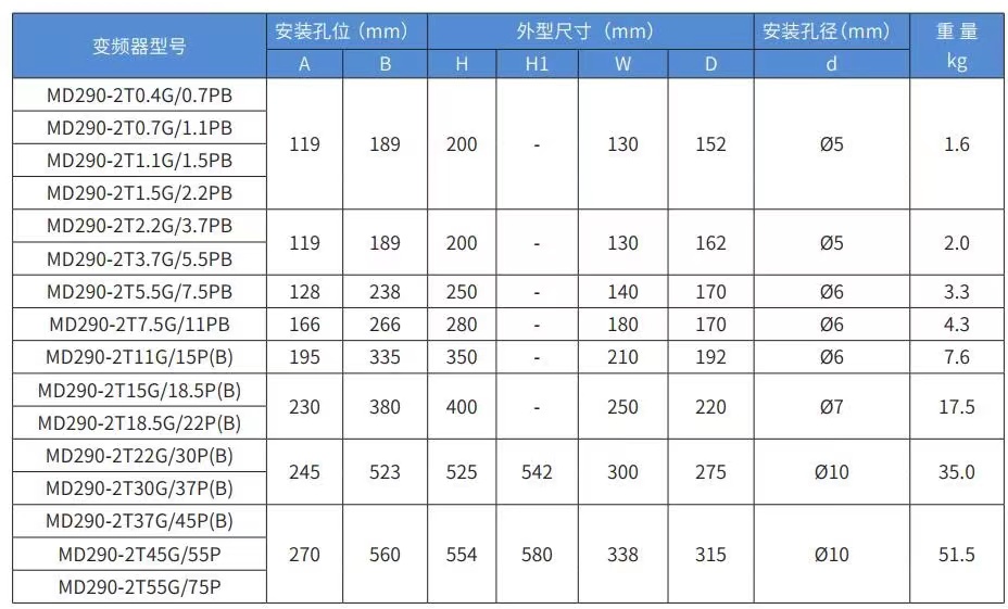
Outline: The main circuit is the power transformation part that provides the adjustable voltage and frequency power source for the induction motor. The main circuit of the inverter can be roughly divided into two categories: Voltage-type is an inverter that converts the DC voltage source to AC, and the filter in the DC circuit is a capacitor. Current-type is an inverter that converts the DC current source to AC, and the filter in the DC circuit is an inductor. It consists of three parts, which transforms the AC power source into DC power.rectifierThe 'flattening circuit', which absorbs the voltage fluctuations generated by the inverter and converter, and the 'inverter', which converts the DC power into AC power.
Inverter:
1. In contrast to the rectifier, an inverter converts direct current power into the required frequency of alternating current power. By making six switch devices conduct and turn off at the specified time, a three-phase AC output can be obtained. For example, a voltage-type PWM inverter is shown to illustrate the switch time and the voltage waveform.
2. The control circuit provides the main circuit with control signals for the supply of an asynchronous motor (voltage and frequency adjustable). It consists of the frequency and voltage 'arithmetic circuit', the 'voltage and current detection circuit' of the main circuit, the 'speed detection circuit' of the motor, the 'amplification drive circuit' for the control signals from the arithmetic circuit, and the 'protection circuit' for the inverter and the motor.
(1)Operational Amplifier Circuit: Compares the external speed, torque, etc., with the current and voltage signals from the detection circuit to determine the output voltage and frequency of the inverter.
(2) Voltage and Current Detection Circuit: Isolated from the main circuit to detect voltage and current, etc.
(3)Drive Circuit: The circuit that drives the main circuit devices. It isolates from the control circuit to make the main circuit devices conduct or cut off.
(4) Speed Detection Circuit: The signal from the speed detector (such as tg, plg, etc.) mounted on the shaft of the asynchronous motor is used as the speed signal, which is then sent to the operation circuit. Based on the instructions and calculations, the motor can be operated at the specified speed.
(5) Protection circuit: Detects the voltage and current of the main circuit, and when abnormal conditions such as overloading or overvoltage occur, in order to prevent damage to the inverter and asynchronous motor, the inverter stops working or suppresses the voltage and current values.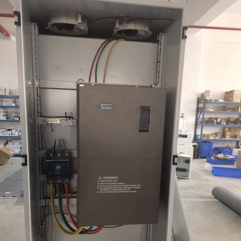
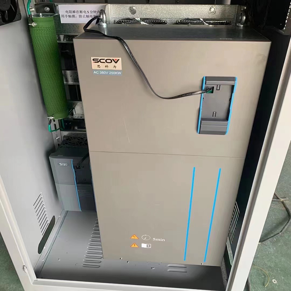
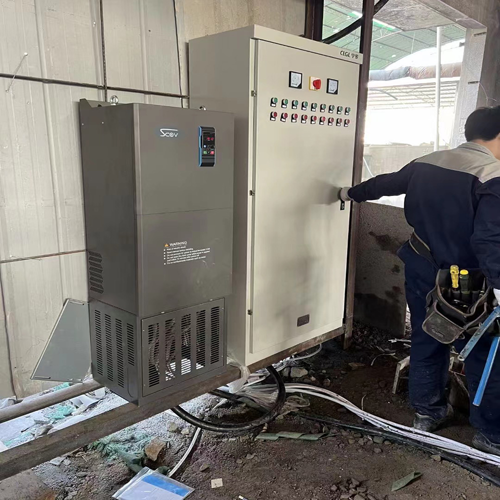
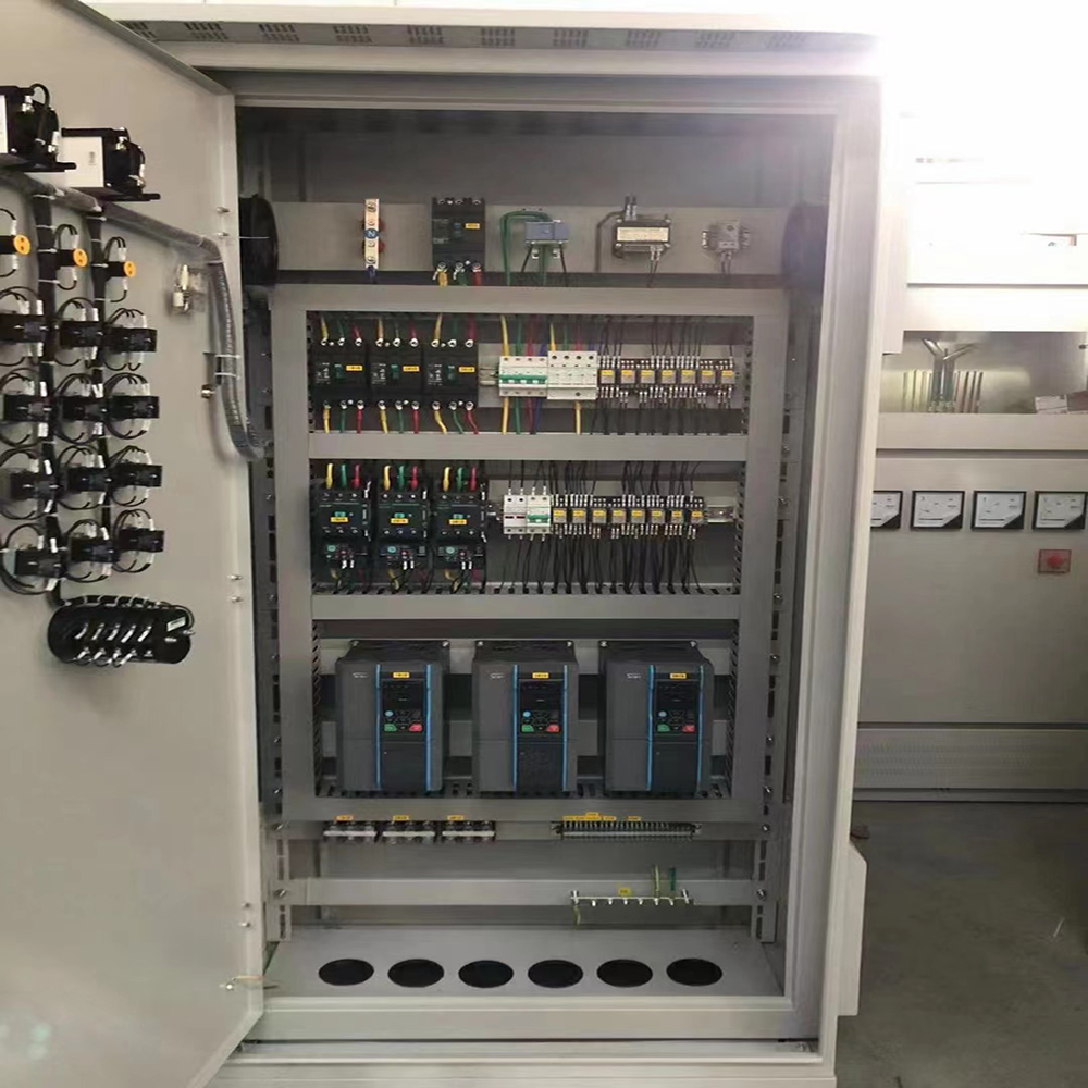
Update time:
TOP