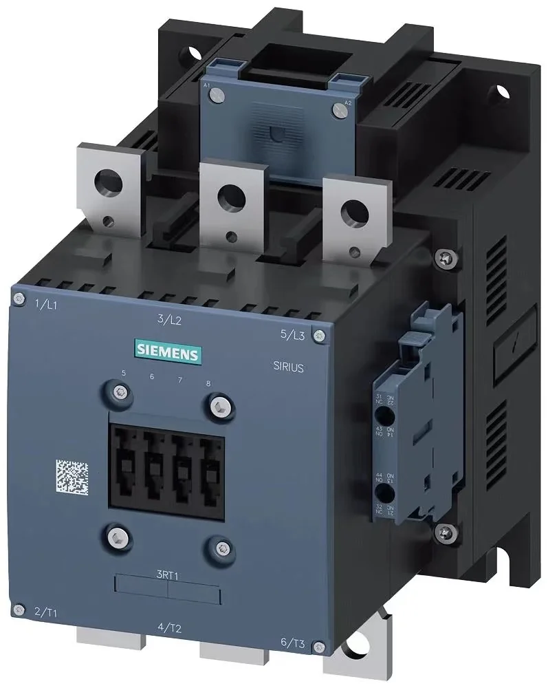
Power contactor, AC-3e/AC-3 300 A, 160 kW/400 V AC (50-60 Hz)/DC UC: 110-127.
V 3 pole, auxiliary contact 2 NO+2 NC drive: traditional main circuit: wire control circuit and auxiliary circuit: screw
Pin end
Product brand name SIRIUS
Product name power contactor
Product type name 3RT1
Comprehensive technical data
Structural ruler ⼨S10 of contactor
Product expansion
● No function module for communication
● The auxiliary switch is
When loss power [W] current is measured,
● 66 W at AC in hot transport state.
At AC, each electrode is 22 W in thermal transport state.
● Typical load current share is 7.4 W.
Loss power calculation type electrode correlation orthomorphism
isolation voltage
● The pollution degree of the main circuit is 1 000 V at 3 o'clock.
● The measured value of auxiliary circuit with pollution degree of 3 is 500 V.
Impact resistance voltage energy
● The measured value of the main circuit is 8 kV.
● Measured value of auxiliary circuit is 6 kV.
The maximum allowable voltage for safety isolation conforms to EN between the coil and the main contact.
60947-1
690 V
When resisting the impact of impact waves
● 8,5g/5 ms, 4,2g/10 ms at AC time.
● 8,5g/5 ms, 4,2g/10 ms at DC.
Impact-resistant sinusoidal impact
● 13,4g/5 ms, 6,5g/10 ms at AC time.
● 13,4g/5 ms, 6,5g/10 ms at DC.
Mechanical service life (switching cycle)
● Typical contactor 10 000 000
● Typical 5,000,000 contactors with electrically adapted auxiliary switch blocks
● Typical contactor with auxiliary switch block 10 000 000
environmental conditions
The installation degree exceeds the maximum of 2 000 m above the level.
ambient temperature
● During transportation-25 ...+60 C
● Storage period-55 ...+80 C.
The maximum relative air humidity is 10%
When the relative air humidity is 55℃, the maximum value is 95% according to IEC 60068-2-30.
Mount/fix/outline ruler
The mounting position can be rotated by+/-90 for vertical mounting flat, and tilted forward and backward by+/-22.5 for vertical mounting flat.
Fastening type bolt fixation
Degree 210 mm
Width 145 mm
Depth 202 mm
The spacing must be observed
● Single-row mounted
—20 mm forward
-10 mm upward.
—10 mm downward.
—0 mm laterally
● To the grounding part
—20 mm forward
-10 mm upward.
—10 mm laterally
—10 mm downward.
● To components with voltage
—20 mm forward
-10 mm upward.
—10 mm downward.
—10 mm laterally
Connection/terminal
Electrical connection specification
● At the end of the main circuit.
● Bolt connection for auxiliary and control circuits.
● The contactor is bolted to the auxiliary contact.
● Bolt connection of electromagnetic coil
Width connecting guide rail 25 mm
Thickness connecting guide rail 6 mm