Search history
Clear allSearch by image
XDrag and drop an image here or upload an image
Max 5MB per image
UploadSign In | Join
Search history
Clear allSearch by image
XDrag and drop an image here or upload an image
Max 5MB per image
UploadSign In | Join
X Email Mobile
 sapphire blue
|
CN¥ 71.3 |
Yiwu Maoxie Firm 14yr.
Contacts stone Chat
Mobile 86-15325953595
E-mail 18006551840@163.COM
15397595552

WhatsApp 15325953595
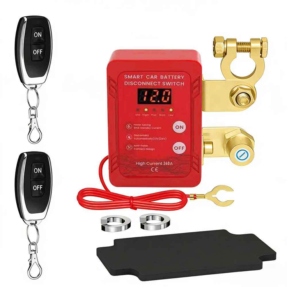
Pack quantity: 30 pcs
Volume: 0.024 CBM
Packaging:
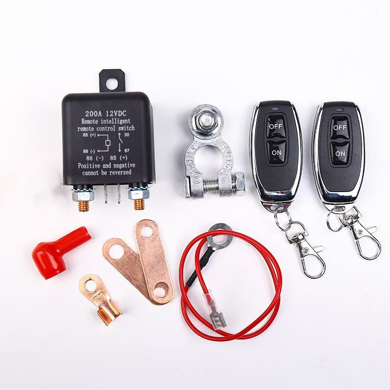
The English-Chinese manual is as follows:
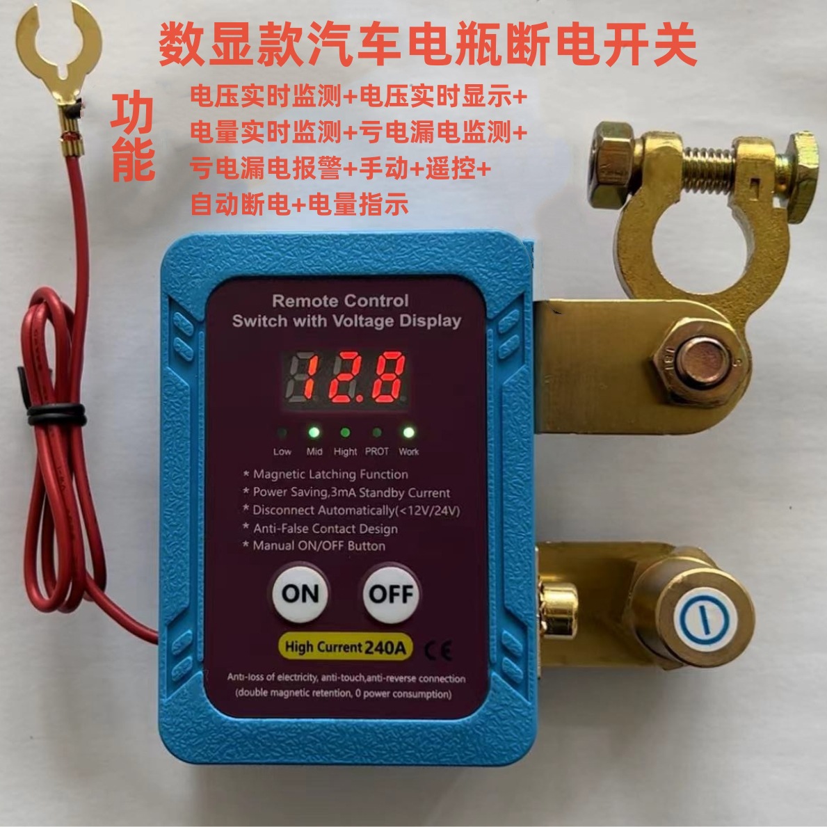
Magnetic hold RF switch instruction
Product specifications and characteristics
1. Operating voltage range: 6–30VDC
2. Adaptive 1₂V vehicle system and 2₄V Vehicle System
3. Automatic alarm when the defect threshold is reached, and automatic battery disconnection
4. Frequency: 4.33.92 MHz, matching self-locking mode
5. Indicator display (ON and OFF)
6.700uA ultra-low standby power consumption
7. Driving process and ignition error trigger protection
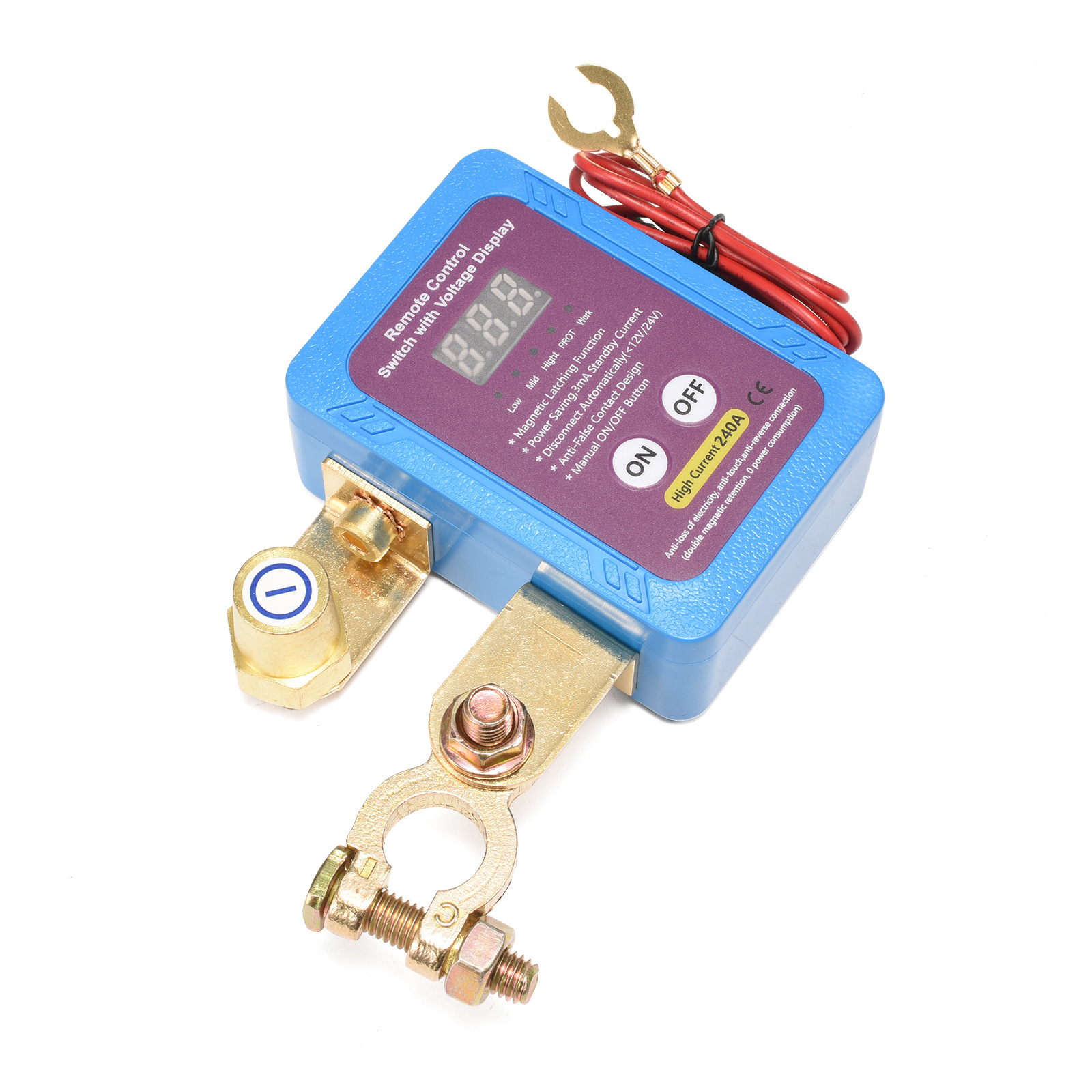
Product parameters
1. Operating temperature: -20 degrees to +100.
2. Rated current switch: 250A
3. Instantaneous current switching: 500A
4. Loss protection threshold: 1.1–1.8 V ± 0.2 V / 2.3 V ± 0.2 V
5. Power loss delay: 60 seconds; alarm; 120 seconds automatic disconnection
6. Standby current: 700uA
Notes:
1. The operating voltage range of the remote control and equipment can be paired normally
2. The operating voltage range of the manual ON/OFF button allows for the connection and disconnection of equipment.
3. If the supply voltage is less than 6V or more than 3V, the equipment will automatically shut down and disconnect.
4. If the power supply voltage falls below the protection threshold voltage (1.1–1.8 V/2.3–2.2 V) for 60 seconds, an alarm will be triggered; after 120 seconds, the device will automatically disconnect to protect the battery.
5. If the voltage is higher than 13.3 V (12V system) or 26.2 V (24V system), the RF remote control will fail to prevent the remote control button from accidentally touching the remote control during operation, which will result in a power failure.
6. The voltage range is 6–18V, and the self-identification is a 12V vehicle system that operates in response to the 12V system threshold.
7. Voltage range of 18–30V for self-identification in the 24V vehicle system, in response to the 24V system threshold operation
8. When the battery voltage is relatively high, the system enters the trip-triggered protection state.
9. When the battery voltage is relatively low, the system enters the protection state due to ignition misfire.
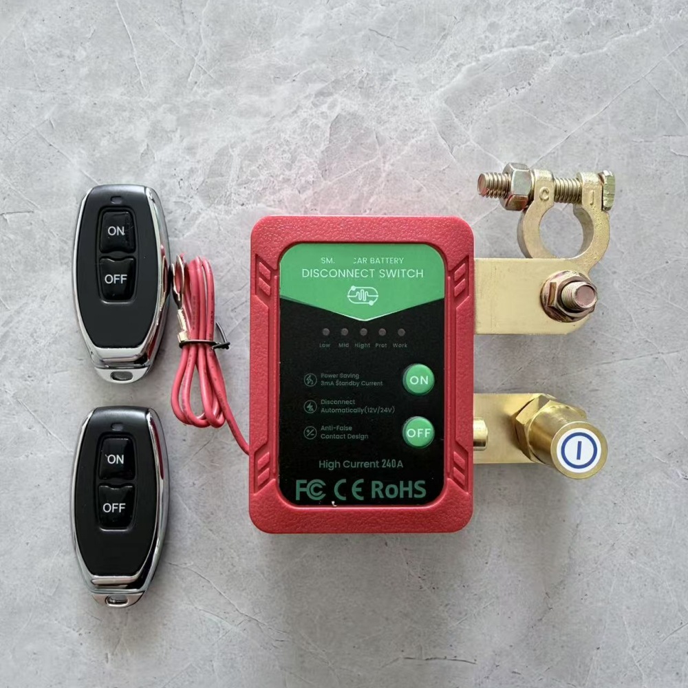
Remote control matching instructions
1. Interlock mode (applicable to vehicle system control) – continuously press the manual key on the code for 3 seconds; the indicator light will flash 3 times to enter the learning state. Press the key on the remote control, and then the indicator light will flash three times after the code is successfully matched. Next, press another button on the remote control to successfully code the system after the indicator lights flash three times.
2. After entering the learning state, the learning code indicator light did not receive the remote control signal to automatically terminate the learning state within 30 seconds.
3. Clear code: Long-press the manual key ON on the code indicator until it flashes 8 times, indicating that the clear code is complete (long-press the manual key ON until the indicator flashes 3 times, 4 times, 5 times, and 8 times in sequence; where flashing 3 times indicates the interlock mode learning state, flashing 4 times indicates the self-lock mode learning state, flashing 5 times indicates the click-move mode learning state, and flashing 8 times indicates the clear code state)
4.A set of 20 codes can be paired with 10 different remotes at the same time.
3. Clear code: Long-press the manual key ON on the code indicator until it flashes 8 times, indicating that the clear code is complete (long-press the manual key ON until the indicator flashes 3 times, 4 times, 5 times, and 8 times in sequence; where flashing 3 times indicates the interlock mode learning state, flashing 4 times indicates the self-lock mode learning state, flashing 5 times indicates the click-move mode learning state, and flashing 8 times indicates the clear code state)
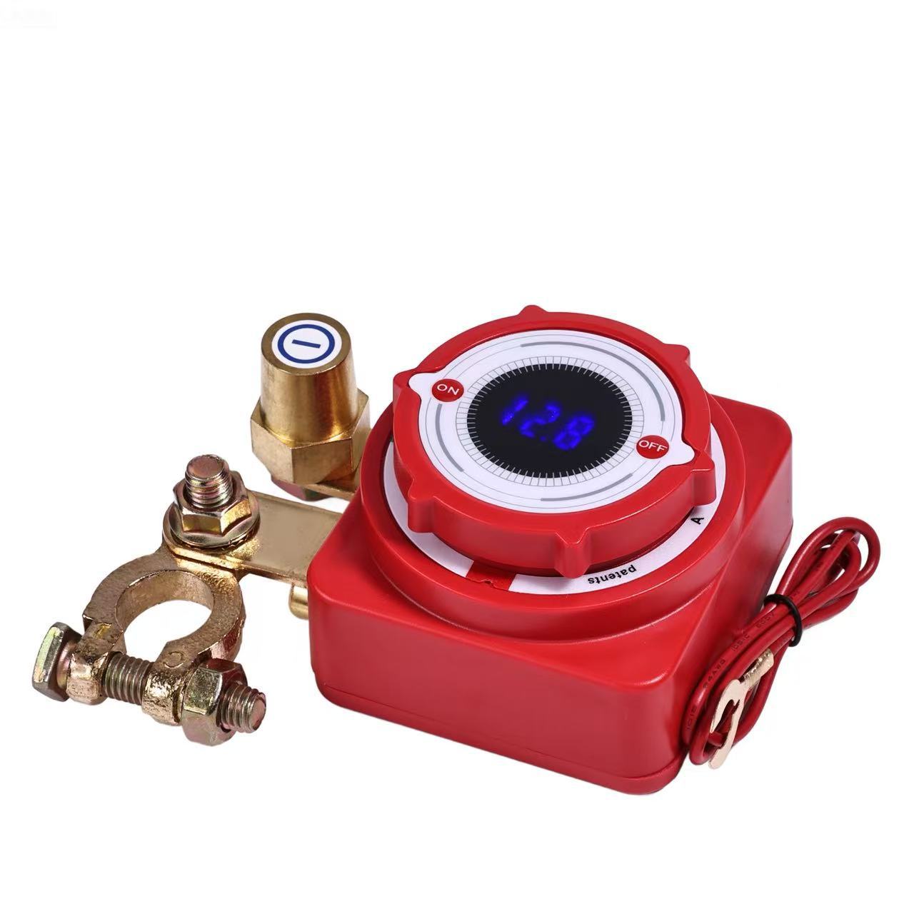
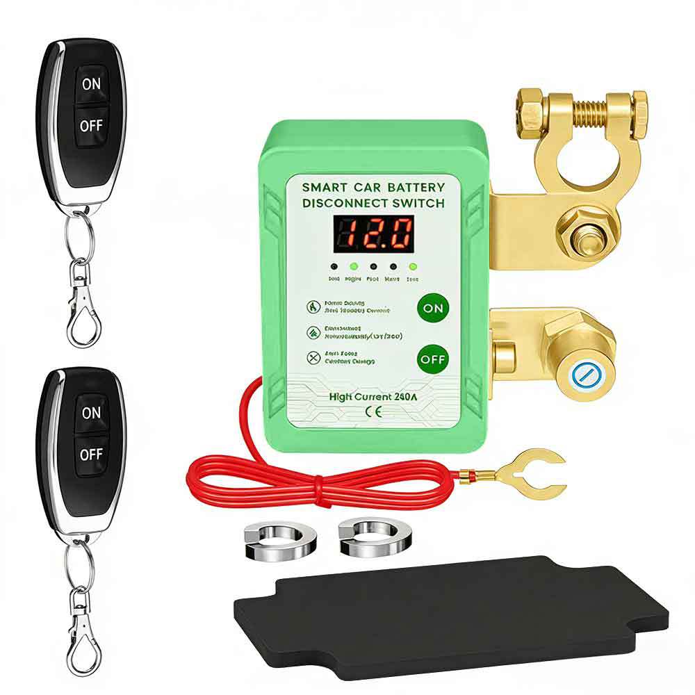
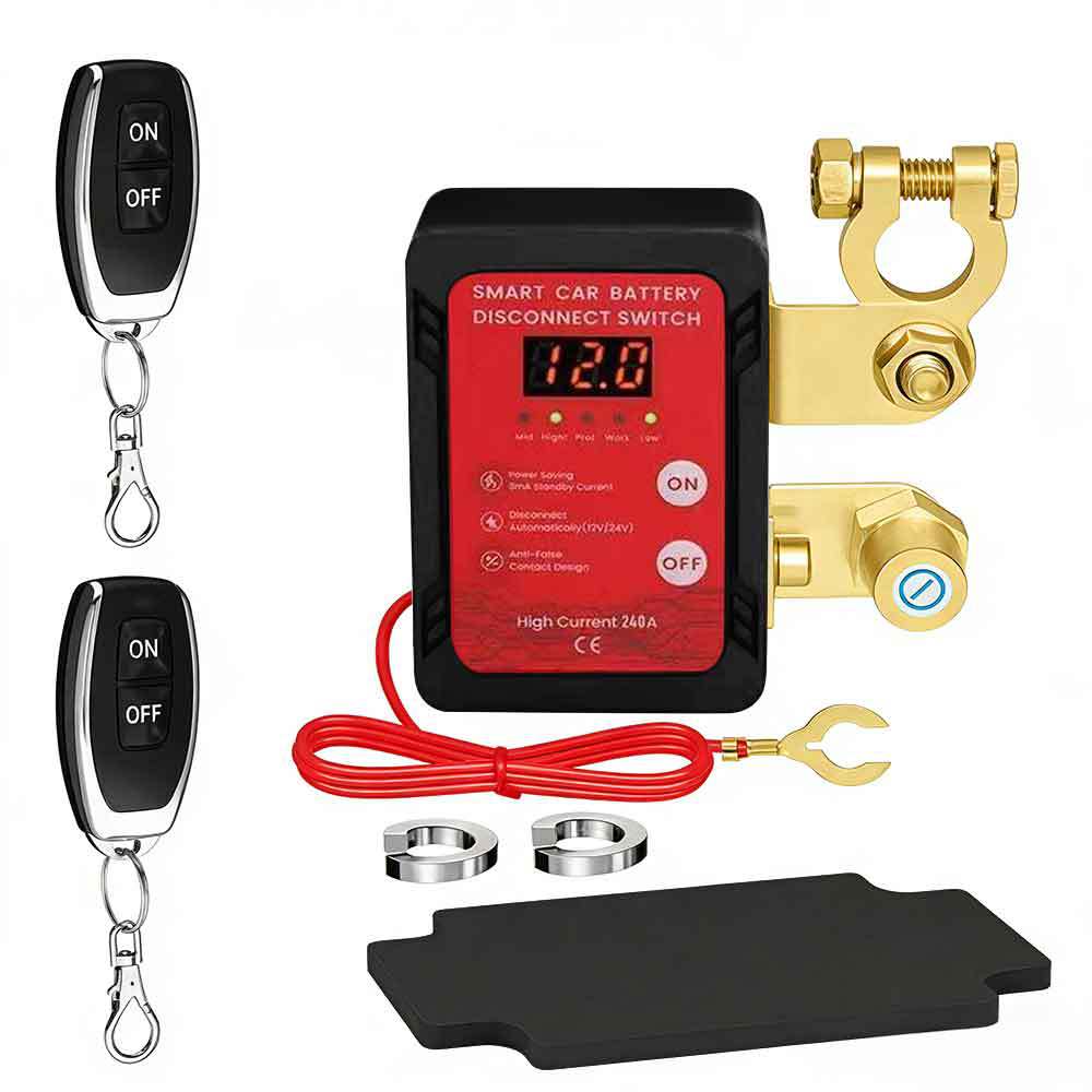
Magnetic Hold Automotive Battery Anti-Discharge Intelligent Disconnecter Manual
Product specifications and features
1. Working voltage range: 6–30VDC
2. Adaptive 1.2V vehicle system and 2.4V vehicle system
3. Automatic alarm and automatic disconnection of the battery at low charge threshold
4. Frequency: 4.33.92 MHz, matching self-locking mode
5. Indicator light display (turns on when connected, turns off when disconnected)
6. 6700μA ultra-low standby power consumption
7. Driving process and incorrect ignition trigger protection
Product specifications
1. Operating temperature: -20 degrees Celsius to +100 degrees Celsius
2. Switch rated current: 250A
3. Current at the moment of switching is 500A
4. Discharge protection threshold: 1.8V ± 0.2V / 2.3V ± 0.2V
5. A 60-second delay during low battery state triggers an alert, and it automatically disconnects after 120 seconds.
6. Standby current: 700uA
Note:
1. Within the working voltage range, the remote control can be paired with the device normally.
2. Within the working voltage range, manual ON/OFF buttons can connect and disconnect the device.
3. Devices with a power supply voltage below 6V or above 30V will automatically shut down and disconnect.
4. If the power supply voltage falls below the protection threshold voltage (1.1–1.8V/2.3–2.2V) for 60 seconds, an alert will be displayed; if it persists for 120 seconds, the device will automatically disconnect to protect the battery.
5. The voltage must be higher than 13.3V (for 12V system) or 26.2V (for 24V system). Radio frequency remote control fails to prevent accidental activation of buttons during driving, which could cause power loss.
6. When the voltage range is between 6–18V, it is automatically identified as a 12V vehicle system, operating at the 12V system threshold point.
7. When the voltage range is between 18–30V, it is automatically identified as a 24V vehicle system, operating at the 24V system threshold point.
8. During driving, the relatively high battery voltage causes the system to mistakenly enter a protection state.
9. When igniting, the battery voltage is relatively low, causing the system to enter a false ignition protection state
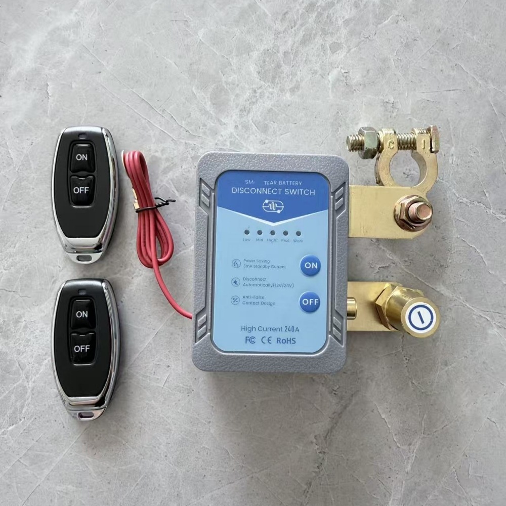
Remote Control Matching Instructions
1. Interlock mode (applicable to vehicle system control) – Press the manual button ON continuously for 3 seconds for the calibration indicator light to flash 3 times to enter the learning state. Press the button on the remote control; after successful calibration, the indicator light flashes 3 times. Then press another button on the remote control; after successful calibration, the indicator light flashes 3 times again.
2. After entering the learning state, if the learning code indicator light does not receive a remote control signal within 30 seconds, it will automatically exit the learning state;
3. Clear codes—hold the manual ON button. The code-checking indicator light flashing 8 times indicates that the code clearing is complete (hold the manual ON button, and the indicator light will flash 3 times, 4 times, 5 times, and 8 times in sequence; where flashing 3 times indicates the interlock mode learning state, flashing 4 times indicates the self-lock mode learning state, flashing 5 times indicates the point-and-go mode learning state, and flashing 8 times indicates the code clearing state).
4. A set of 20 codes for equipment can be paired with 10 different remotes simultaneously.
Update time:


TOP