Search history
Clear allSearch by image
XDrag and drop an image here or upload an image
Max 5MB per image
UploadSign In | Join

Search history
Clear allSearch by image
XDrag and drop an image here or upload an image
Max 5MB per image
UploadSign In | Join
X Email Mobile
YIWU SHUANGLI HARDWARE COMPANY 15yr.
Contacts:lemen Chat
Mobile:86-13506587772
E-mail:2859664980@qq.com
Metal Geardouble-sided card swipingHua Rui BrandIntelligentUnified Lock


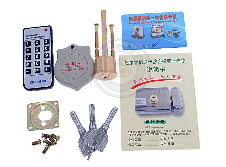
Product Instruction Manual1 piece Management Card1 piece
Functional Features:
1、 Supports 1000 ID cards.
2、Support20个315M学习型Remote control
3、 Entering and exiting the door must use access cards and remote control to unlock, supportingIDOrEMCompatible Card FarHigh-speed sensors, dual read card inside and outside。
4、 Realized the integration of access control host and intelligent electrical mechanical locks.
5、 Compatible with all building intercom systems and access control system unlock signals.
7、 After closing the door, the lock will automatically engage, with visual and audible status indicators, and the door closing process is smooth with no bumping or noise, making it environmentally friendly and green.
8、 The integrated structure design is highly resistant to damage, with a rational circuit and mechanical design that is easy to install, operate, and maintain.
Electrical Performance:
1、 Input Voltage: DC 12V+20%Static Current<80mAAction current<350mA
2、 Xie Pinca unlocking reaction time<0.5S讳瞳距离<20mm
3、 Remote control unlock response time<0.3SRemote control distance>100m
4、 Start-up current<280mA
5、 Alarm Output Current<1500mAAlarm readiness rate:"≥" is the symbol for "greater than or equal to" in English.99.9%
6、 Work environment temperature:-40"℃" is the symbol for Celsius temperature scale.-70Celsius, temperature95%
7、 Anti-interference: IEC801-5Standard
8、 Anti-surgeIEC801-5Standard
Installation Method:

1. Drilling Pre-holes
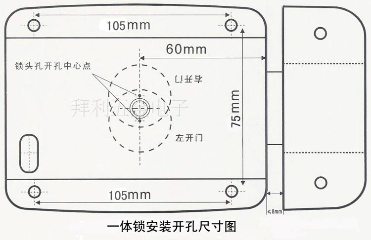
a. Drill a hole at a height of about 1 meter from the ground, 60mm from the edge of the door, for the lock head with a diameter of φ28.5+0.5.
b. Expand (dig) the step hole with a diameter of φ36×3.5 inward from the center of the hole, to install the locking head mounting plate (commonly known as the three-eye plate).
Part Two: Installing the Lock Cylinder
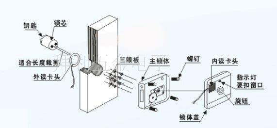
a. Turn the key teeth upward and insert it into the lock hole. Then, slide the lock head inward, fitting the outer lock ring onto it. Simulate entering the door body hole, and insert the tail through the installation board (the three-eye board hole).
b. Observe the tail length of the door body, which is about 10-15mm; if it is greater than 10-15mm, it should be cut to meet the dimensions.
c. Repeat 'a' to transfer the simulated action to formal assembly. Note: If the door leaf thickness does not meet the standards, it can be thickened to meet the lock installation requirements. (The minimum thickness should be 30 mm).
d. Install and tighten two M5×45 three-piece screws (the length can be cut after simulation comparison, making the depth of the screw into the lock head screw hole be 8-14 mm is best).
e. Secure the three-eye plate to the lock with screws, then tighten the four wood screws at the corners of the three-eye plate. While installing the screws, make sure to frequently rotate the key to ensure that the tail can rotate freely and align with the large hole in the three-eye plate.
III. Install the main lock body (the lock should be in the unlocked state)
a. Open the rear cover (screw in the lock tongue exit surface).
b. Connect the power supply and unlocking line into the hole (the φ10 hole in the upper right corner) with a length of about 100mm.
c. Lock alignment. Insert the lock shaft hole into the lock head tail in the indicated position, ensuring proper insertion.
d. Tighten the 4 main locking screws, turning them in while trying to turn the key, and tighten the screws as long as the key rotates freely.
e. Test the key to unlock the lock, and the lock tongue should be able to extend and retract flexibly (the lock tongue can be inserted into the key hole of the lock head at any position, and can turn flexibly to reset and then normally remove).
Fourthly, connect the power cord.
Connect the power and unlocking line according to the instructions on the circuit board to complete the wiring.
Five, Lockset Cover
a. Tilt the lid slightly, insert the positioning clip of the lid into the corresponding slot of the main lock body, and then fit the 5x5 square shaft of the knob into the square hole of the rotating shaft, adjust the lid to be parallel, and then install the external lid fixing screws.
b. After the rotation knob is rotated freely, the main lock body assembly is complete, and the trial operation (opening and closing the lock) is to be conducted.
Sixth, Install the Latch
a. Simulate the location of the lock latch on the door frame in the direction corresponding to the main lock body (the secondary lock body), and ensure that the gap between the lock latch and the tongue hole is uniform. After drawing the outline, remove the lock latch. (Note: The gap between the lock latch and the shell edge of the main lock body should be ≤5mm).
b. Loosen and remove the screw of the fixed bracket on the side of the latch, and then fix the bracket to the door frame at the center position of the latch shape line drawn on the door frame. Then, fit the latch onto the bracket and secure the screw in place.

Update time:
TOP